Conversion system of multi-winding permanent magnetic direct-drive generator and conversion control method
A technology of permanent magnet direct drive and flow system, which is applied in the directions of wind power generation, AC power input conversion to AC power output, and AC power input conversion to DC power output, etc., which can solve phase current mutual interference, generator phase current distortion, Wind turbine vibration and other problems, to achieve the effect of suppressing current distortion, reducing mutual influence, and improving control performance
- Summary
- Abstract
- Description
- Claims
- Application Information
AI Technical Summary
Problems solved by technology
Method used
Image

Examples
Embodiment 1
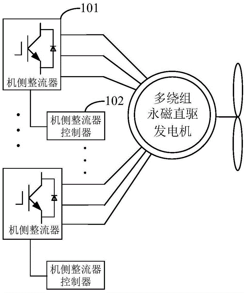
[0025] figure 2 It is a structural schematic diagram of the converter system of the multi-winding permanent magnet direct drive generator according to Embodiment 1 of the present invention, such as figure 2 As shown, the converter system includes: a plurality of machine-side rectifiers 101, and a plurality of machine-side rectifier controllers 102 corresponding to the multiple machine-side rectifiers 101, and each machine-side rectifier 101 is connected with the multi-winding permanent magnet direct drive power generation Multiple machine-side rectifier controllers 102 control the switching of the corresponding machine-side rectifiers 101, so that the switching frequencies of every two adjacent machine-side rectifiers 102 differ by a predetermined frequency interval.
[0026] Specifically, for example, assuming that there are n machine-side rectifiers and n machine-side rectifier controllers corresponding to the n machine-side rectifiers one-to-one, the predetermined frequen...
Embodiment 2
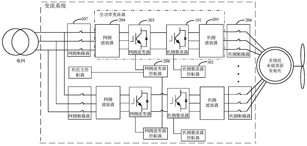
[0029] image 3 It is a structural schematic diagram of the converter system of the multi-winding permanent magnet direct drive generator according to the second embodiment of the present invention, such as image 3 As shown, the converter system includes: multiple machine-side rectifiers 101, multiple machine-side rectifier controllers 102 corresponding to the multiple machine-side rectifiers 101, multiple grid-side inverters 203, multiple grid-side filters 204 and multiple generator-side filters 205, the full-power converter includes: grid-side inverter 203, grid-side filter 204, generator-side rectifier 101, and generator-side filter 205, that is, the converter system includes A plurality of full power converters, and the plurality of full power converters adopt a parallel topology. In this embodiment, the full power converter includes a grid-side filter, a grid-side inverter, the generator-side rectifier, and the generator-side filter. Generally speaking, in practical ap...
Embodiment 3
[0040] Figure 4 It is a structural schematic diagram of the converter system of the multi-winding permanent magnet direct drive generator according to the third embodiment of the present invention, as shown in Figure 4 As shown, the converter system includes: a plurality of generator-side rectifiers 101, a plurality of generator-side rectifier controllers 102 corresponding to the plurality of generator-side rectifiers 101, a grid-side circuit breaker 208, a grid-side filter 204, a A grid-side inverter 203, a plurality of generator-side filters 205 and a plurality of generator-side circuit breakers 206, wherein one end of the grid-side circuit breaker 207 is connected to the grid, and the other end of the grid-side circuit breaker 207 is connected to the grid-side filter 204, one end of each machine-side circuit breaker 206 is connected to a set of windings of the multi-winding permanent magnet direct drive generator, and the other end of each machine-side circuit breaker 206...
PUM
 Abstract
Description
Claims
Application Information
PatSnap Eureka turns technology decisions into work you can execute. Powered by our Innovation Knowledge Graph, it runs expert workflows across engineering, life sciences, materials and intellectual property. Get your review-ready output in minutes.


