A High Efficiency Drum Magnetic Separator

A drum-type, high-efficiency technology, applied in the direction of magnetic separation, solid separation, chemical instruments and methods, etc., can solve the problems that affect the processing capacity of a single machine, low processing capacity of magnetic separator, low recovery rate of concentrate, etc., and achieve improvement Single processing capacity, improve the effect of controlling tailings grade and improving concentrate recovery rate

Active Publication Date: 2017-02-01
LUANXIAN SIJIAYING IRON ORE OF HEBEI IRON & STEEL GROUP
View PDF12 Cites 1 Cited by
  • Summary
  • Abstract
  • Description
  • Claims
  • Application Information

AI Technical Summary

Problems solved by technology

The disadvantages of the drum magnetic separator with built-in magnetic system mainly include the following points: First, the drum magnetic separator with built-in magnetic system has a small separation area and a short separation belt, which leads to low processing capacity of the magnetic separator. The concentrate recovery rate in the ore is low, while the iron ore contained in the tailings is of high grade; secondly, due to the large mass of the magnetic system, the magnetic system is built in the drum, resulting in a large spindle load of the drum, which makes the drum type It is difficult to achieve super-large magnetic separators, which affects the increase in the processing capacity of a single machine
Because the drum-type magnetic separator with built-in magnetic system has the above shortcomings, which limits the production capacity of the magnetic separator, it is necessary to improve the drum-type magnetic separator with built-in magnetic system to meet the needs of large-scale production

Method used


Image

  • A High Efficiency Drum Magnetic Separator
  • A High Efficiency Drum Magnetic Separator
  • A High Efficiency Drum Magnetic Separator

Examples


Embodiment Construction

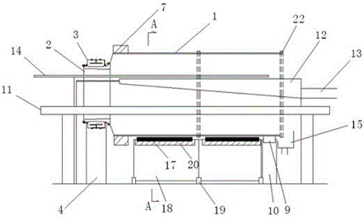
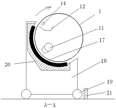
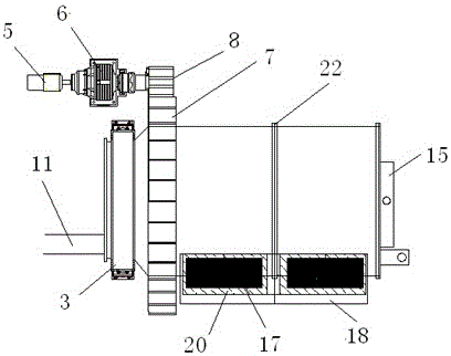
[0019] The present invention includes a drum 1, a rotating shaft 2, a rotating bearing 3, a bearing housing 4, a motor 5, a reducer 6, a large ring gear 7, a pinion 8, an idler 9, an idler bracket 10, an ore feeding pipe 11, and a concentrate Bucket 12, ore unloading water pipe 14, tailings collection tank 15, magnetic system 17 and magnetic system trolley 18. The structure of the present invention is very different from the structure of the existing drum type magnetic separator. The magnetic system 17 is arranged outside the drum 1, and the ore feeding pipe 11, the unloading water pipe 14 and the concentrate bucket 12 are placed on the drum. within 1.

[0020] figure 1 , 2 , 3 shows that the front end of the drum 1 is connected with the hollow rotating shaft 2, and the rotating shaft 2 is installed on the bearing seat 4 through the rotating bearing 3. The cylinder at the connection between the drum 1 and the rotating shaft 2 is a tapered mouth. The large ring gear 7 is set...


PUM


Abstract

The invention provides a high-efficiency drum type magnetic separator and belongs to the technical field of magnetic separation equipment, which is used for efficient mineral separation. According to the technical scheme of the invention, the front end and the rear end of a drum are respectively supported by a rolling bearing and a carrying roller. The drum is driven to rotate by a speed reducer and a motor. A mineral feeding tube and a mineral-discharge water tube extend into the body of the drum through the front end of the drum. A mineral concentrating bucket is arranged below the mineral-discharge water tube. The discharge end of the mineral concentrating bucket extends out of the rear end of the body of the drum. A tailings collecting tank is arranged below the rear end of the drum. A magnetic system is fixedly arranged below the external side of the drum. The magnetic system is opposite to the outer wall of the drum. According to the invention, the magnetic system is arranged outside the drum, so that the action area and the action strength of the magnetic system are improved. Therefore, the sorting area is greatly increased. Meanwhile, the concentrate recovery rate is conveniently improved, and the tailings grade is conveniently controlled. Based on the external arrangement of the magnetic system, the supporting problem of the magnetic system is solved. In this way, the drum type magnetic separator can be made to be ultra-large scale, and the processing capacity of each single high-efficiency drum type magnetic separator on ores is greatly improved. The need of the large-scale production can be met.

Description

technical field [0001] The invention relates to a drum-type magnetic separator with high-efficiency ore-dressing capacity, and belongs to the technical field of magnetic separation equipment. Background technique [0002] In the production process of iron ore, magnetic separation is an important production link of beneficiation. At present, there are many kinds of magnetic separators, which can be divided into dry type high magnetic field magnetic separator, flat ring type high magnetic field magnetic separator, SHP wet type high magnetic field magnetic separator, vertical ring wet high magnetic field magnetic separator. The general structure of these magnetic separators is to use a drum with a built-in magnetic system. During the rotation of the drum, the magnetic system will absorb the iron-containing particles in the ore on the outer wall of the drum. The water pipe or scraper is collected into the concentrate tank for discharge. The disadvantages of the drum magnetic s...

Claims


Application Information

Patent Timeline
Patent Type & Authority Patents(China)
IPC IPC(8): B03C1/14B03C1/30
Inventor 张春舫南世卿王磊
Owner LUANXIAN SIJIAYING IRON ORE OF HEBEI IRON & STEEL GROUP
Why Eureka
Try Eureka