A roadway surrounding rock control method based on drilling pressure relief and grouting strengthening

A technology of drilling pressure relief and surrounding rock control, applied in tunnels, tunnel linings, earthwork drilling and mining, etc., can solve problems such as inability to coordinate, save costs and procedures, promote the stability of roadway surrounding rock, and facilitate surrounding rock grouting strengthening effect

Inactive Publication Date: 2017-02-01
HENAN POLYTECHNIC UNIV
View PDF6 Cites 2 Cited by
  • Summary
  • Abstract
  • Description
  • Claims
  • Application Information

AI Technical Summary

Problems solved by technology

[0005] The present invention aims at the lack of synergy between the stress reduction zone formed around the roadway and the grouting strengthening of the surrounding rock in the existing roadway drilling pressure relief, and proposes a roadway surrounding rock control technology in which the drilling pressure relief and grouting strengthening are coordinated. It aims to solve the problem of grouting strengthening and re-bearing of the broken surrounding rock after the pressure relief of the roadway drilling, realize the synergy between the stress transfer of the surrounding rock of the roadway and the strengthening of the bearing, so as to reduce the construction steps, reduce the support cost, and achieve the purpose of stabilizing the surrounding rock of the roadway

Method used


Image

  • A roadway surrounding rock control method based on drilling pressure relief and grouting strengthening
  • A roadway surrounding rock control method based on drilling pressure relief and grouting strengthening
  • A roadway surrounding rock control method based on drilling pressure relief and grouting strengthening

Examples


Embodiment Construction

[0026] In order to make the object, technical solution and advantages of the present invention clearer, the present invention will be further described in detail below in conjunction with the accompanying drawings and examples.

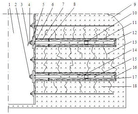
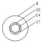
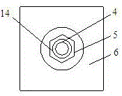
[0027] The invention provides a roadway surrounding rock control technology in which drilling pressure relief and grouting strengthening are coordinated.

[0028] Such as Figure 1~3 Shown, the specific embodiment of the present invention comprises the following steps:

[0029] Step 1, in the large-deformation anchoring roadway 1 supported by the anchor net, the basic parameters such as the position, quantity, aperture and depth of the pressure relief drilling 16 are determined according to the deformation of the surrounding rock;

[0030] Step 2, using a drilling rig to drill holes at designated locations, the pressure relief drilling holes 16 are perpendicular to the wall surface, and the depth reaches the elastic zone 9;

[0031] Step 3, after th...


PUM


Abstract

The invention discloses a tunnel surrounding rock control technology combining pressure relief and slip-casting reinforcement. The control technology comprises following steps of determining basic parameters of positions, numbers, diameters and depths of pressure relief drilling holes according to deformation conditions of surrounding rocks in an anchor supporting big deformation anchoring tunnel; using a drilling machine to performing hole drilling in an assigned position until reaching an elastic area; arranging a slip-casting steel pipe system formed by a front blocking ring, a connection hoop, a back blocking ring and a slip-casting steel pipe in the pressure relief drilling holes; using a measuring and detecting device to perform continuous observation for deformation rate of the diameters of the pressure relief drilling holes so as to determine slip-casting materials, ratio of slurry, slip-casting pressure and slip-casting time; stopping observation when the deformation rate of the diameters of the pressure relief drilling holes increases suddenly; fastening the slip-casting steel pipe and connecting the outer end part of the slip-casting steel pipe with a slip-casting pump via a slip-casting soft pipe and a hole-containing sealing plug; starting the slip-casting pump so as to allow the slurry to enter a spare hole filling area and be pressed into cracks of the surrounding rocks; and after the slip casting is finished, rotating fastening screws so as to carry out secondary fastening, thereby finishing the whole construction process.

Description

technical field [0001] The invention relates to a large-deformation roadway surrounding rock control technology, which belongs to the field of geotechnical engineering anchoring support, and in particular relates to the roadway surrounding rock control technology of underground mining engineering roadway surrounding rock decompression stress release and grouting strengthening bearing. Background technique [0002] After the roadway is excavated in the coal-rock mass, due to the breaking of the original rock stress, a stress concentration area will be formed around the roadway. If the bearing capacity of the shallow surrounding rock is less than the redistributed stress, the surrounding rock of the roadway will be unstable. Most of the methods used are to anchor and support the surrounding rock of the roadway, so that the strength of the shallow surrounding rock can be strengthened under the pre-tightening force of the bolt, but it will also cause the surrounding rock of the r...

Claims


Application Information

Patent Timeline
Patent Type & Authority Patents(China)
IPC IPC(8): E21D11/10E21D20/02E21B7/04E21B47/08
Inventor 辛亚军安定超李梦远
Owner HENAN POLYTECHNIC UNIV
Why Eureka
Try Eureka