
Water level measuring system for boiler drum and measuring and checking method thereof

A technology of water level measurement and boiler steam drum, applied in the direction of displaying liquid level indicator through pressure measurement, etc., can solve problems such as changing the relationship between water level and differential pressure thermodynamics, overflow of differential pressure range, and inconsistent readings after adjustment. Standardization of device data, less heat loss, and light weight

Active Publication Date: 2015-09-09
郭春堂 +1
View PDF5 Cites 20 Cited by
  • Summary
  • Abstract
  • Description
  • Claims
  • Application Information

AI Technical Summary

Problems solved by technology

When the water level indication value of the water level gauge is inaccurate, it is adjusted with the zero linear adjustment device of the differential pressure transmitter. After adjustment, the calibration value of the differential pressure transmitter is changed, and the working differential pressure range has a dead zone, and the range power overflows. During the maintenance and calibration, the readings of the differential pressure transmitter before and after the adjustment did not match, which not only changed the thermodynamic relationship between the water level and the differential pressure, but also invalidated the calibration record

Method used


Image

  • Water level measuring system for boiler drum and measuring and checking method thereof
  • Water level measuring system for boiler drum and measuring and checking method thereof
  • Water level measuring system for boiler drum and measuring and checking method thereof

Examples


Embodiment Construction

[0048] The present invention will be further described in detail below in conjunction with the accompanying drawings and embodiments.

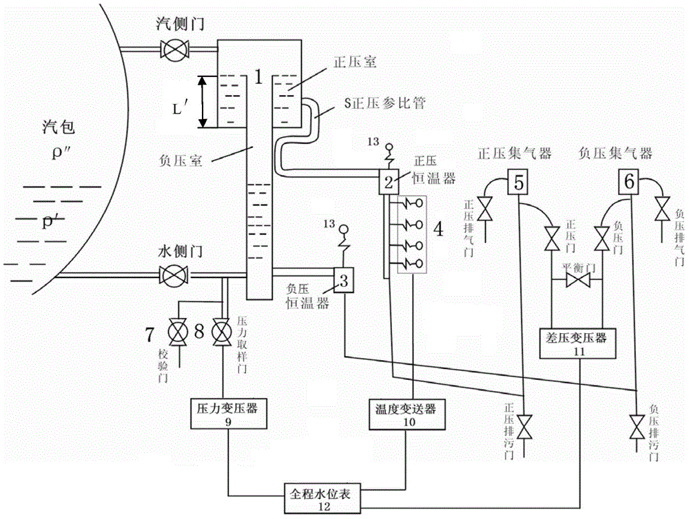
[0049] The present invention has tested this steam drum water level measuring system on the 220t / h high pressure furnace and 670t / h super high pressure furnace. The working environment temperature is 5-90 degrees. The water level measuring system comprises a water level measuring device 1, a thermostat, an average density measuring device 4, a pressure sampling door 8, a pressure transmitter 9, a temperature transmitter 10, a differential pressure transmitter 11 and a full-range water level gauge 12; the water level The measuring device 1 is connected with the steam side door and the water side door of the boiler drum, connected with the differential pressure transmitter 11 through the thermostat, and connected with the pressure transmitter 9 through the pressure sampling door 8; the thermostat is connected with the average density measurement...


PUM


Abstract

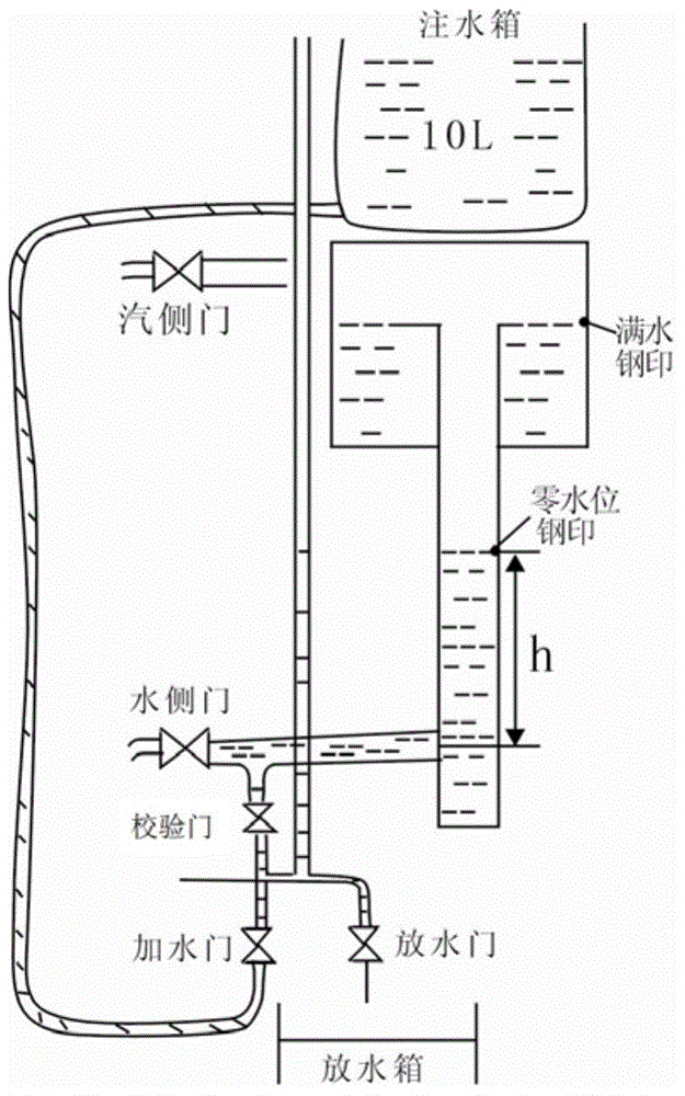
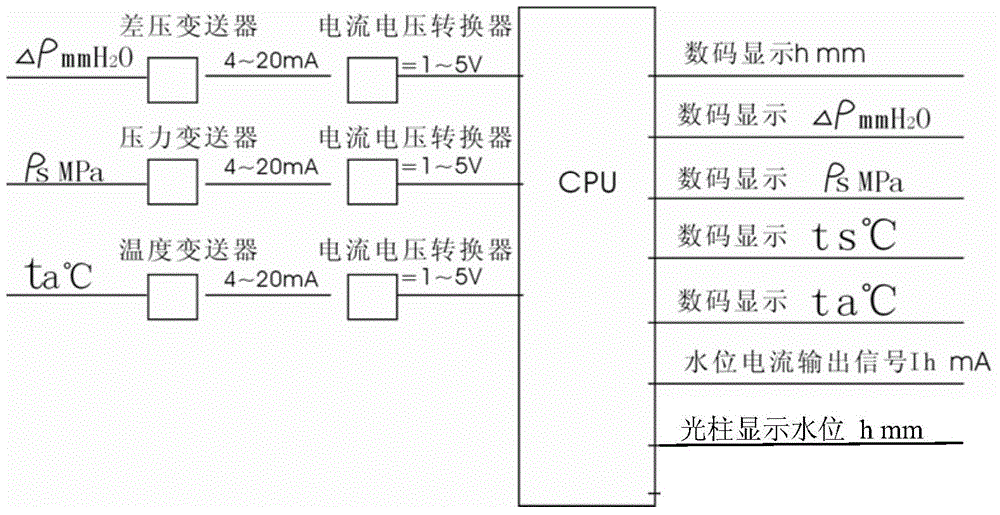
The invention relates to a water level measuring system for a boiler drum. The water level measuring system comprises a water level measuring device, a thermostat, a mean density measurer, a pressure sampling door, a pressure transmitter, a temperature transmitter, a differential pressure transmitter and a full water level indicator, wherein the water level measuring device is connected with the stream side door and the water side door of the drum, connected with the differential pressure transmitter by the thermostat, and also connected with the pressure transmitter by the pressure sampling door; the mean density measurer connected with the thermostat is connected with the temperature transmitter; the pressure transmitter, the temperature transmitter and the differential pressure transmitter are all connected with the fill water level indicator. The water level measuring method obtains the real-time water level by measuring the differential pressure, saturation pressure and room temperature. The checking method checks the system by checking the door and a water injection box. Condensed water generated by the stream side door also flows into the water level measuring device, and jointly flows back into the drum with the condensed water in the device; therefore, the heat loss is less, the water temperature at the lower part of the device is improved, and the measurement accuracy is also improved. The water level measuring system for the boiler drum is small in volume and light in weight, and recycles the heat.

Description

technical field [0001] The invention relates to the field of boiler steam drum water level measurement, in particular to a water level measurement system capable of real-time, dynamic and accurate measurement of the water level in the steam drum, a measurement method thereof, and a calibration method of the water level measurement system. Background technique [0002] Drum water level measurement technology involves multiple disciplines such as thermodynamics, heat transfer, fluid mechanics, material mechanics, thermal measurement technology, measurement error theory, etc. It is a comprehensive measurement of multi-function, multi-independent variable, dynamic, real-time, and transient physical quantities process. In the measurement process, there are many uncertain additional errors, and random errors are difficult to separate. [0003] Over the years, there has been no "standard measurement transfer" for the measured value of the water level of the steam drum, and there i...

Claims


Application Information

Patent Timeline
Patent Type & Authority Applications(China)
IPC IPC(8): G01F23/14
Inventor 郭春堂郭洪涛
Owner 郭春堂
Learn More