
Correlation function-based moving-target parameter estimation method

A correlation function and parameter estimation technology, which is applied in the field of signal processing, can solve problems such as system complexity, blind speed of detection methods, and difficult image focus, and achieve high-precision speed parameter estimation, high speed detection accuracy, and strong applicability.

Active Publication Date: 2015-09-09
BEIHANG UNIV
View PDF4 Cites 16 Cited by
  • Summary
  • Abstract
  • Description
  • Claims
  • Application Information

AI Technical Summary

Problems solved by technology

[0004] 1. The principle of moving target detection based on a single-channel system is to directly detect the characteristics of the echo signal of the moving target, but for a single-channel system, clutter suppression is difficult to achieve, and a large amount of clutter in the echo makes the moving target difficult to detect;
[0005] 2. The principle of moving target detection based on multi-channel system is to suppress clutter first, and then detect moving targets based on the signal after clutter suppression. The main processing methods include phase center offset technology DPCA, along-track interference ATI , space-time adaptive processing STAP, etc., but this detection method has the problems of blind speed and speed ambiguity, and the system is more complicated;
[0007] The image is defocused due to the azimuth velocity of the target, and the Doppler frequency shift is caused by the radial velocity, and when the target has a large velocity, the image is difficult to focus, which increases the difficulty of detection

Method used


Image

  • Correlation function-based moving-target parameter estimation method
  • Correlation function-based moving-target parameter estimation method
  • Correlation function-based moving-target parameter estimation method

Examples


Embodiment

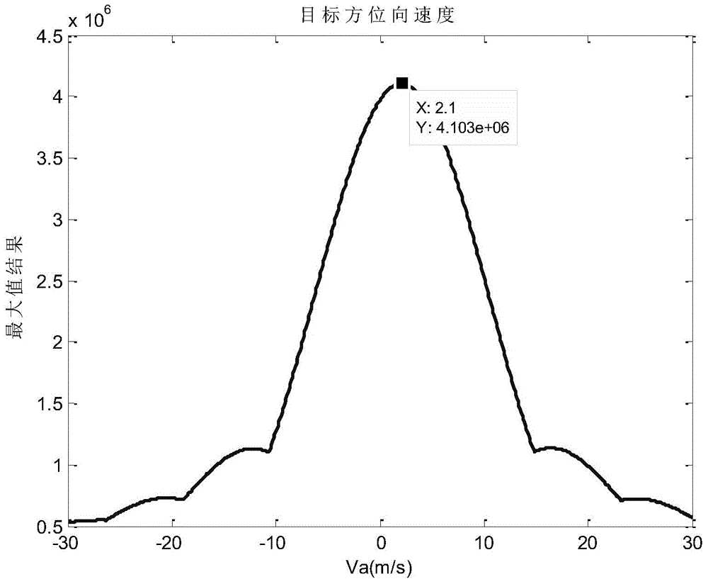
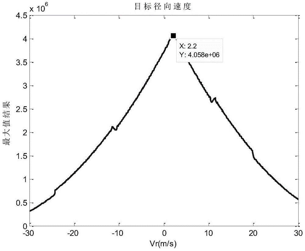
[0118] This embodiment proposes a method for estimating moving target parameters based on correlation functions. The simulation scene is a 1×1 dot matrix. According to the actual speed and direction of the point target, the detection is divided into three situations: assuming that the target only has azimuth speed; assuming that the target has only Radial Velocity; assume the target has both azimuth and radial velocities. The imaging parameters involved in the imaging process are shown in Table 1.

[0119] Table 1 embodiment parameters

[0120]

[0121]

[0122] This embodiment specifically includes the following steps:

[0123] Step 1: Read in the simulation complex data S based on the two-dimensional original echo simulation of the moving target in the spaceborne side-looking strip SAR mode 0 and the corresponding imaging parameters. Among them, S 0 is a two-dimensional complex array with a size of 8192×4096, and the specific imaging parameters are shown in Table 1...


PUM


Abstract

The invention discloses a correlation function-based moving-target parameter estimation method. The method comprises steps of 1: reading in original moving target echo data and related imaging parameters; 2: performing Fourier transform processing for azimuth; 3: performing compensation by multiplying azimuth and CS factors; 4: performing Fourier transform processing for range distance; 5: multiplying the range distance and distance compensation factors so as to process distance compressing processing; 6: performing Fourier inversion processing for range distance; 7: performing correlation function processing for distance-Doppler domain; 8: performing Fourier inversion processing for azimuth; 9: performing zero filling for frequency domain, and adding sampling in time domain so as to perform interpolation processing or related processing results and get the maximum value; and 10: estimating target speed via the related maximum value. According to the invention, estimation of target azimuth and radial speed are simultaneously achieved, precision for estimation speed of moving targets of a current satellite born SAR is increased, and a novel detection method is provided.

Description

technical field [0001] The invention belongs to the field of signal processing, in particular to a method for estimating parameters of a moving target based on a correlation function in the field of Synthetic Aperture Radar (SAR). Background technique [0002] SAR is a high-resolution imaging radar that can obtain large-area high-resolution radar images. At the same time, it is an active remote sensor that works in the microwave frequency band. It is not restricted by the region. It can implement the remote sensing imaging observation task of the earth all day and all day, and can penetrate natural vegetation, artificial camouflage, etc. Compared with traditional optical images , significantly improving the radar's information capture capability. Therefore, SAR has been widely used. Ground and sea moving target detection technology is an important direction in the field of modern radar tactical reconnaissance at home and abroad. As early as during World War II, the Dopple...

Claims


Application Information

Patent Timeline
IPC IPC(8): G01S13/90
CPCG01S13/58G01S13/9011G01S13/9029G01S13/904
Inventor 陈杰王亚敏杨威赵松涛匡辉
Owner BEIHANG UNIV
Learn More