Press nail structure of epoxy cast dry-type transformer

A technology of dry-type transformer and epoxy casting, which is applied in the field of transformer manufacturing, and can solve the problems of many machined parts, difficulty in guaranteeing welding quality, and high verticality requirements between nail nuts and clamps.

Inactive Publication Date: 2015-09-09
ZHENJIANG TIANLI TRANSFORMER
View PDF7 Cites 1 Cited by
  • Summary
  • Abstract
  • Description
  • Claims
  • Application Information

AI Technical Summary

Problems solved by technology

The advantage of this structure is that the structure is reliable, and the disadvantage is that there are many machined parts, high requirements on the perpendicularity between the nail nut and the clamp, the welding quality is difficult to guarantee, and the work efficiency is low

Method used


Image

  • Press nail structure of epoxy cast dry-type transformer
  • Press nail structure of epoxy cast dry-type transformer
  • Press nail structure of epoxy cast dry-type transformer

Examples


Embodiment Construction

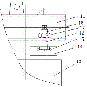
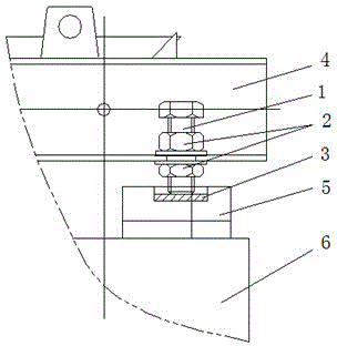
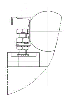
[0013] An epoxy cast dry-type transformer nail structure, see figure 2 and image 3 , the nail structure includes a compression bolt 1, a lock nut 2 and a pressure plate 3, the compression bolt is arranged in the through hole at the bottom of the upper clamp 4 and pressed tightly on the pressure plate 3, and the pressure plate 3 is arranged on the upper pad 5 In the rectangular slotted hole, the pressing plate is a flat steel plate. Two locking nuts 2 are sleeved on the compression bolt 1 and are located on both sides of the through hole at the lower part of the upper clip. The inner diameter of the through hole at the bottom of the upper clamping part is compatible with the compression bolt, and the aperture of the through hole at the lower part of the upper clamping part is slightly larger than that of the compression bolt, so there is no need to weld the clamping screw nut. The pressure nail is replaced by the pressure bolt; the pressure bolt and the lock nut are all sta...


PUM


Abstract

The invention discloses a press nail structure of an epoxy cast dry-type transformer. The press nail structure comprises a compression bolt, a locking nut and a press plate, the compression bolt is arranged in a through hole in the lower part of an upper clamp piece and firmly compresses the press plate, the press plate is arranged in a long slot hole in an upper cushion block, and the locking nut sleeves the compression bolt and is located at two sides of the through hole in the lower part of the upper clamp piece. The compression structure is easy to assemble and operate; the assembly reliability is fully guaranteed, and the production requirements are satisfied.

Description

technical field [0001] The invention belongs to the field of transformer manufacturing and relates to an epoxy casting dry-type transformer pressing nail structure. Background technique [0002] The nail structure of the traditional epoxy resin dry-type transformer is as follows: figure 1 shown. A round hole is opened at the bottom of the upper clip 11, and the nail nut 12 is welded in the hole. After the coil 13 is assembled, place the upper pad 14, place the pressure bowl 15 in the circular groove on the upper end of the upper pad, then screw the pressure nail 16 into the pressure nail nut, apply force to the coil through the pressure bowl, and play Compression action, finally with the locking nut 17 positioning the whole structure to complete the assembly. The advantage of this structure is that the structure is reliable, and the disadvantage is that there are many machined parts, high requirements on the perpendicularity between the nail nut and the clamp, the welding...

Claims


Application Information

Patent Timeline
Patent Type & Authority Applications(China)
IPC IPC(8): H01F27/30H01F41/04
Inventor 李云孙国平邹遵武
Owner ZHENJIANG TIANLI TRANSFORMER
Why Eureka
Try Eureka