
Electrically tunable four-passband filter based on double layered resonator

A resonator and four-pass-band technology, applied in the field of microwave devices, can solve the problems of difficulty in implementation, difficult to expand the structure to more pass-bands, complex structure of the ESC, and achieve the effect of reducing the volume

Active Publication Date: 2015-09-09
XIDIAN UNIV
View PDF3 Cites 18 Cited by
  • Summary
  • Abstract
  • Description
  • Claims
  • Application Information

AI Technical Summary

Problems solved by technology

The current electronically tuned filters are mainly concentrated in the fields of single passband and double passband, and the three-passband or even four-passband electronically tuned filters are more difficult to implement due to their complex structure.
[0003] In January 2009, E.E.Djoumessi et al. published "Varactor-tuned quarter-wavelength dual-bandpass filter" in the IET Microwave Antennas Propagation journal (Vol.3, no.1, pp.117–124, 2009), proposing an electronic Adjustable dual-passband microstrip filter, the filter can realize the continuous electric adjustment of two passbands, but it is difficult to extend the structure to more passbands; in 2009, Ko-Wen Hsu et al. .1041-1044, 2009.) published "Design of a Novel Four-Band Microstrip Bandpass Filters using Double Layered substrate", and proposed a four-band microstrip filter based on a double-layer structure, which can realize Four passbands, but cannot achieve fast adjustable frequency

Method used


Image

  • Electrically tunable four-passband filter based on double layered resonator
  • Electrically tunable four-passband filter based on double layered resonator
  • Electrically tunable four-passband filter based on double layered resonator

Examples


Embodiment Construction

[0019] Embodiments of the present invention are described in detail below in conjunction with accompanying drawings:

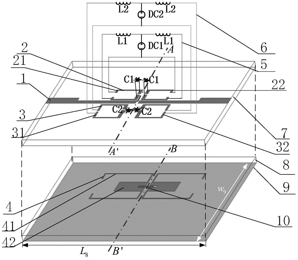
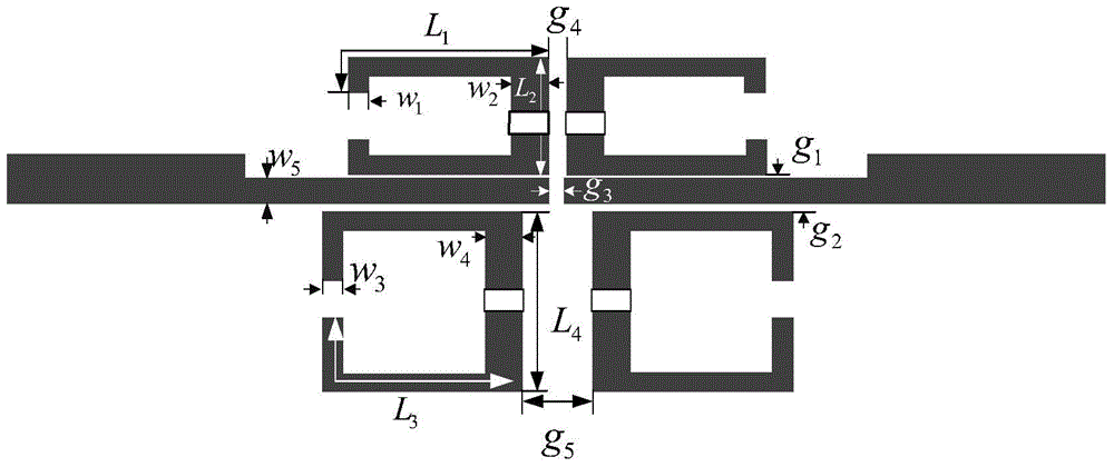
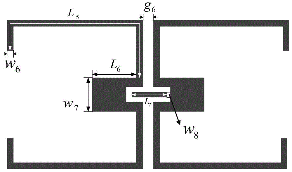
[0020] refer to figure 1 , the present invention includes a first microstrip dielectric substrate 7, a pair of parallel coupled feeders 1, a first adjustable step impedance resonator 2, a second adjustable step impedance resonator 3, a first DC bias circuit 5, a second DC bias circuit 6 , second microstrip dielectric substrate 8 , stub loaded resonator 4 , transmission line 10 and metal ground plate 9 . in:

[0021] A pair of parallel coupled feeders 1, a first adjustable stepped impedance resonator 2, and a second adjustable stepped impedance resonator 3 are arranged on the first microstrip dielectric substrate 7, and a pair of parallel coupled feeders 1 are horizontally located on the first microstrip In the middle of the tape dielectric substrate 7, the first adjustable stepped impedance resonator 2 and the second adjustable stepped impedance resonator 3 ...


PUM


Abstract

The invention discloses an electrically tunable four-passband filter based on a double layered resonator, and mainly solves the problems that the number of passbands of a traditional electrically tunable filter is small, adjustable passband bandwidth is not constant, the out-of-band rejection degree is poor and the volume is large. The electrically tunable four-passband filter based on the double layered resonator includes a pair of parallel coupling feeder lines (1) and a pair of adjustable stepped impedance resonators (2, 3) which are arranged on an upper microstrip medium substrate (7), and a branch loading resonator (4) and two direct current biasing circuits (5, 6) which are arranged on a lower microstrip medium substrate (8), wherein the two direct current biasing circuits (5, 6) are connected to two ends of the adjustable stepped impedance resonators (2) and (3), thereby realizing continuously adjustability of a third passband and a fourth passband, and the branch loading resonator (4) realizes fixing of a first passband and a second passband. The electrically tunable four-passband filter based on the double layered resonator is small in size and high in out-of-band rejection degree, can realize four passbands, realizes continuous adjustability of the third passband and the fourth passband under the condition that the bandwidth is basically maintained unchanged, and can be used for a wireless communication system.

Description

technical field [0001] The invention belongs to the technical field of microwave devices, in particular to a microstrip electrically adjustable four-pass band filter, which can be used for a radio frequency front end of a wireless communication system. Background technique [0002] With the rapid development of modern communication technology, the contradiction of spectrum resource congestion has become increasingly prominent. In order to efficiently utilize limited spectrum resources, it is usually required that the RF front-end, such as filters, have the characteristics of fast tuning. The electric tuning filter changes the capacitance value of the varactor diode by controlling the DC bias voltage, thereby changing the resonant frequency and realizing fast switching at different operating frequencies. In addition, in order to achieve different service requirements in multiple frequency bands, the wireless communication system needs to use filters to select in-band working...

Claims


Application Information

Patent Timeline
Patent Type & Authority Applications(China)
IPC IPC(8): H01P1/203
Inventor 吴边刘津林苏涛赵勋旺李龙
Owner XIDIAN UNIV
Learn More