Current-constant driving light modulation circuit of LED of single-stage power supply
A technology of constant current drive and dimming circuit, which is applied in the direction of electric lamp circuit layout, electric light source, light source, etc., can solve the problems of complicated circuit and high cost, large loss of two-stage circuit, and high cost, which is conducive to intelligent control and reduces circuit Loss, the effect of reducing the cost of dimming
- Summary
- Abstract
- Description
- Claims
- Application Information
AI Technical Summary
Problems solved by technology
Method used
Image
Examples
Embodiment 1
[0073] Please refer to Figure 4-6 , Embodiment 1 of the present invention is:
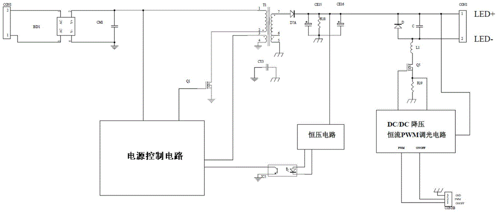
[0074] A single-stage power supply LED constant current drive dimming circuit, including a power supply module, a PSR IC power supply control module, a transformer, a control module, an opening and closing control module, a signal conversion module, a PWM transmission module, at least one LED load and external dimming device.
[0075] The power module is connected to one end of the primary coil of the transformer, and the power control module is connected to the other end of the primary coil of the transformer through the MOS transistor Q1; the secondary coil of the transformer is connected to the LED load; The opening and closing control module is connected with the PWM transmission module; the opening and closing control module is connected with the PWM transmission module through a signal conversion module; the signal conversion module and the PWM transmission module are externally connected w...
Embodiment 2
[0076] Please refer to Figure 4-5 , on the basis of embodiment one, embodiment two of the present invention is:
[0077] Such as Figure 5 As shown, the control module includes an output current adjustment circuit, an output voltage control circuit and a VCC power supply circuit;
[0078] The output current adjustment circuit includes resistors R33, R34, R28, R29, R30, R31, capacitors C17, C18, C19 and photoelectric isolator IC5; when the LED circuit is normal and does not dim, the PSR IC power control module controls the output current of the power module, The primary current generated by MOS tube Q1 generates a voltage feedback to the PSR IC power control module through R23. The power control module outputs the corresponding driving waveform from the GATE pin according to the parameters such as the turns ratio of the transformer, so that the LED circuit power supply realizes constant current.
[0079] The output current adjustment circuit receives the PWM signal generated...
Embodiment 3
[0083] Please refer to Figure 4 and 6 , on the basis of embodiment one, embodiment three of the present invention is:
[0084] The secondary control of the LED circuit includes an on-off control module, a signal conversion module and a PWM transmission module; specifically:
[0085] The signal conversion module is preferably a 0-10V to PWM signal module, which is produced by a three-stage operational amplifier circuit, including integrated IC3 (1)-(7) pins, resistors R62, R61, R60, R50, R52, R58, R59, R77, R68, R69, R72, capacitors C52, C50, C53, C51, C54, C56, diode D8, regulator tubes ZD4, ZD5. The first two operational amplifiers form a sawtooth wave generation circuit. The charge and discharge of resistor R62 and capacitor C52 determine the frequency of the sawtooth wave, which is the same as the frequency of the output PWM signal; resistors R60 and R61 determine the amplitude of the sawtooth wave, in order to be compatible with 10V For voltage comparison, the amplitud...
PUM
 Abstract
Description
Claims
Application Information
 - R&D
- Intellectual Property
- Life Sciences
- Materials
- Tech Scout
- Unparalleled Data Quality
- Higher Quality Content
- 60% Fewer Hallucinations
Browse by: Latest US Patents, China's latest patents, Technical Efficacy Thesaurus, Application Domain, Technology Topic, Popular Technical Reports.
© 2025 PatSnap. All rights reserved.Legal|Privacy policy|Modern Slavery Act Transparency Statement|Sitemap|About US| Contact US: help@patsnap.com


