
Circuit board processing method and circuit board having single-surface hole ring

A processing method and circuit board technology, applied in the direction of multilayer circuit manufacturing, printed circuit components, electrical connection printed components, etc., to achieve the effects of improving utilization, saving outer space, and improving the level of intensification

Active Publication Date: 2015-09-09
SHENNAN CIRCUITS
View PDF4 Cites 4 Cited by
  • Summary
  • Abstract
  • Description
  • Claims
  • Application Information

AI Technical Summary

Problems solved by technology

[0004] Embodiments of the present invention provide a circuit board processing method and a circuit board with a single-sided annular ring to solve the technical problem of how to manufacture a circuit board with a single-sided annular ring

Method used


Image

  • Circuit board processing method and circuit board having single-surface hole ring
  • Circuit board processing method and circuit board having single-surface hole ring
  • Circuit board processing method and circuit board having single-surface hole ring

Examples


Embodiment 1

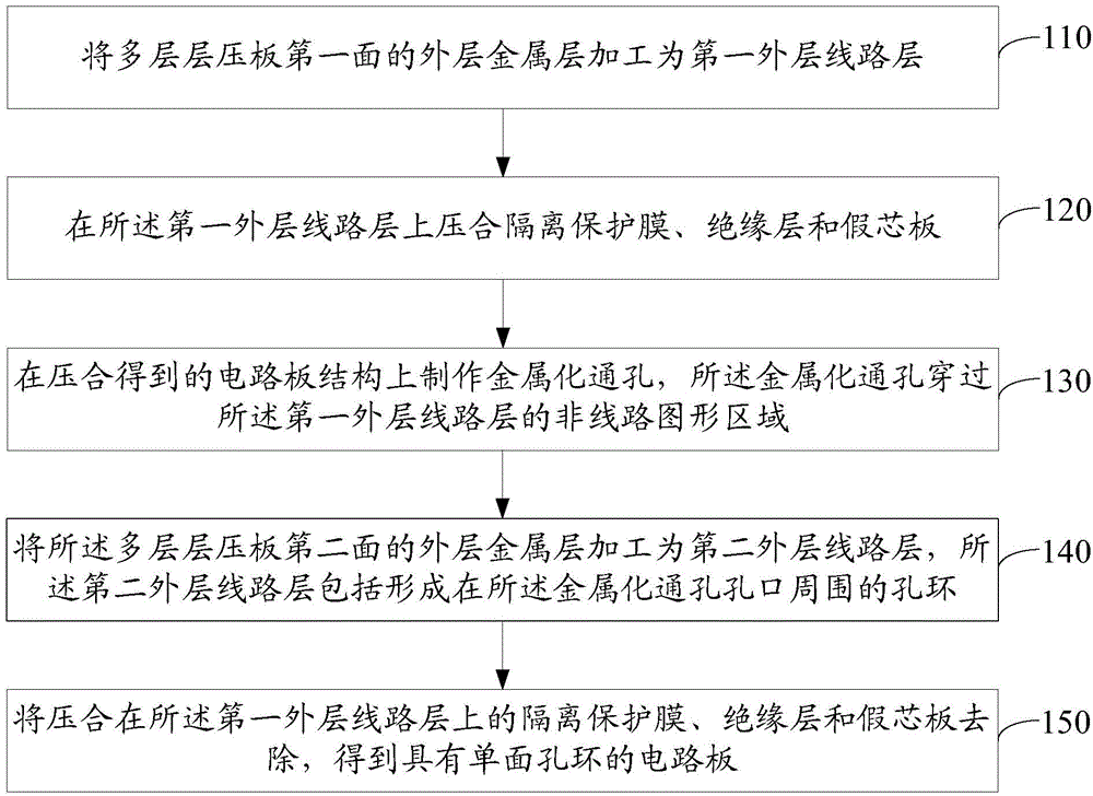
[0026] Please refer to figure 1 , an embodiment of the present invention provides a method for processing a circuit board, which may include:

[0027] 110. Process the outer metal layer on the first side of the multilayer laminate into a first outer circuit layer.

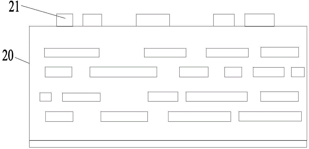
[0028] In the embodiment of the present invention, the circuit board may be a multi-layer laminate based on double-sided copper-clad laminates. Specifically, the multi-layer laminate can be laminated with one or more double-sided copper-clad laminates in the middle, directly laminated copper foil layers on both sides, and laminated an insulating adhesive layer between each layer of double-sided copper-clad laminates and copper foil layers, such as Prepreg, laminated. Among them, before lamination, the double-sided copper clad laminate has been produced with a circuit layer.

[0029] According to the method of the embodiment of the present invention, a metallized through hole with a single-sided annular ring can ...

Embodiment 2

[0054] Please refer to image 3 , an embodiment of the present invention provides a circuit board with a single-sided annular ring.

[0055] The two sides of the circuit board have a first outer circuit layer 21 and a second outer circuit layer 26 respectively, and at least one metallized through hole 25 passes through the circuit board, wherein the metallized through hole 25 passes through the circuit board. The non-circuit pattern area of ​​the first outer circuit layer 21, the second outer circuit layer 26 includes an annular ring 27 formed around the opening of the metallized through hole 25.

[0056] In some embodiments of the present invention, the circuit board includes at least one inner circuit layer, and the metallized through hole 25 is connected to one or more layers of the at least one inner circuit layer.

[0057] To sum up, the embodiment of the present invention discloses a circuit board with a single-sided annular ring. The circuit board to be processed can b...


PUM

PropertyMeasurementUnit
Thicknessaaaaaaaaaa

Abstract

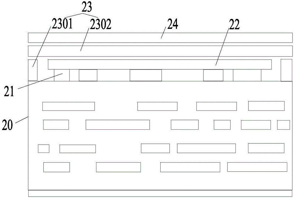
The invention discloses a circuit board processing method and a circuit board having a single-surface hole ring so as to solve the technical problem of how to produce the circuit board having the single-surface hole ring. In some feasible execution modes, the method comprises the following steps: processing an outer-layer metal layer on a first surface of a multilayer laminated board to form a first outer-layer circuit layer; laminating an isolation protection film, an insulating layer and a false core plate on the first outer-layer circuit layer; producing a metalized through hole in a circuit board structure obtained through laminating, the metalized through hole running through a non-circuit graph area of the first outer-layer circuit layer; processing an outer-layer metal layer on a second surface of the multilayer laminated board to form a second outer-layer circuit layer, the second outer-layer circuit layer comprising a hole ring formed around the metalized through hole; and removing the isolation protection film, the insulating layer and the false core plate laminated on the first outer-layer circuit layer to obtain the circuit board having the single-surface hole ring.

Description

technical field [0001] The invention relates to the technical field of circuit boards, in particular to a circuit board processing method and a circuit board with a single-sided annular ring. Background technique [0002] For circuit boards with metallized through holes, in the etching step of forming the surface circuit pattern, the through holes need to be covered with a resist film, so as to prevent the etching liquid from entering and etching and removing the metal plating on the inner wall of the through holes. Therefore, after the etching step, annular rings are formed around the openings of the through-holes on both sides of the circuit board, and the two annular rings located on both sides of the circuit board are connected to the metallized inner walls of the through-holes. [0003] However, with the development of circuit board intensification, the wiring and soldering density on the surface of the circuit board is getting higher and higher. In some application sce...

Claims


Application Information

Patent Timeline
IPC IPC(8): H05K3/46H05K3/42H05K1/02H05K1/11
Inventor 丁大舟刘宝林缪桦
Owner SHENNAN CIRCUITS
Learn More