Flow control module capable of automatically correcting valve opening
A valve opening and flow control technology, applied in the direction of respirators, etc., can solve the problems of large volume, unacceptable and popularized use in hospitals, and low control accuracy
- Summary
- Abstract
- Description
- Claims
- Application Information
AI Technical Summary
Problems solved by technology
Method used
Image

Examples
Embodiment 1
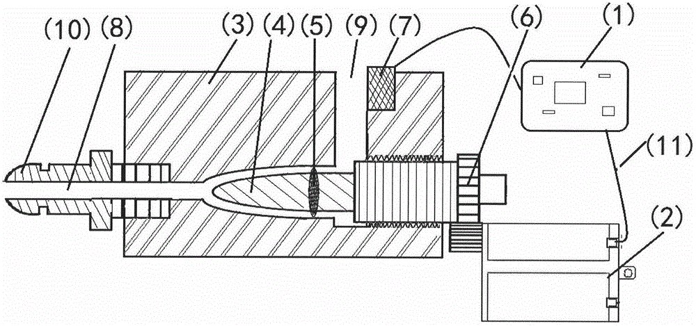
[0020] 1. Embodiment one: the example of the digitally controlled oxygen inhaler prepared by the present invention
[0021] Since the calculation of technical parameters such as valve opening and flow coefficient is relatively complicated, in order to illustrate simple and intuitive examples, this embodiment uses a valve whose flow characteristic is a linear structural characteristic as an example. The linear characteristic refers to the relative flow and relative opening of the valve. The degree is in a linear relationship, that is, the time constant of the flow rate change caused by the change of the unit opening degree. The relative throttling area of the valve is in a linear relationship with the relative opening; determine the calculated flow rate Qλmax=10L / min, Qmin=0.1L / min;
[0022] Valve opening and flow magnification M are shown in Table 1:
[0023] Table 1 Magnification M
[0024] opening
10%
20%
30%
40%
50%
60%
70%
80% ...
Embodiment 2
[0037] Embodiment two: main technical parameter setting in the numerically controlled oxygen inhaler control unit (1) prepared by the present invention
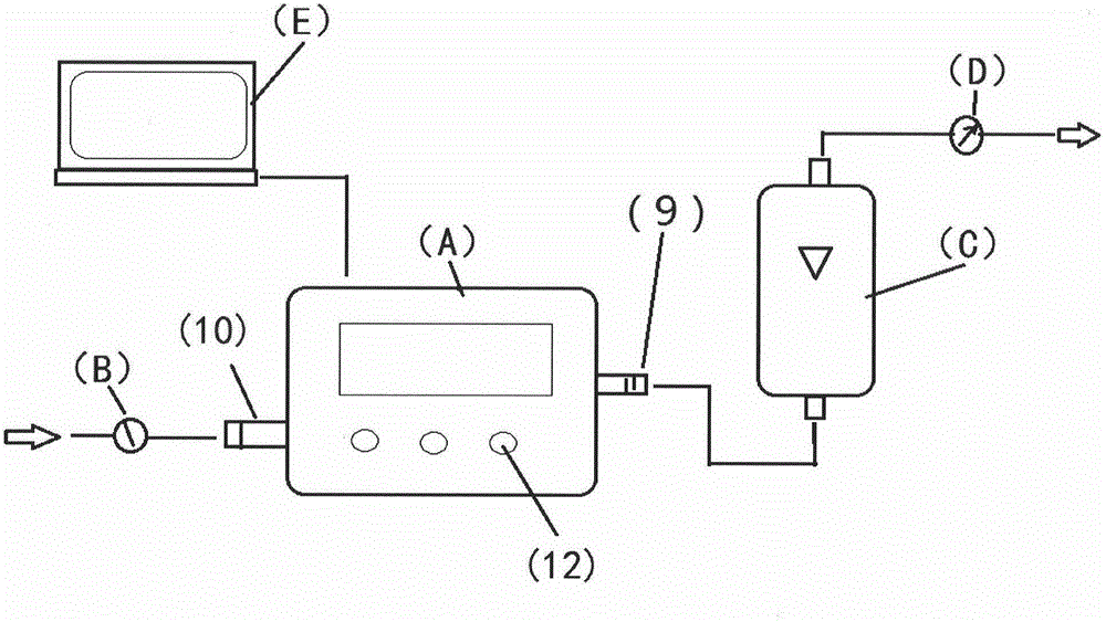
[0038] In the numerically controlled oxygen inhaler (A) control unit (1) prepared in Example 1, the technical parameters are respectively set in the following manner, and the setting equipment includes: 0MPa~0.6MPa adjustable pressure gauge (B), with an accuracy of 2.5 grades; standard Flow meter (C), precision grade 1; oxygen source, terminal air supply pressure not less than 0.3MPa; flow regulating valve (D), upper computer (E), installed ProLinkII software; ambient temperature: 20°C±5°C.
[0039] 1. Valve opening and corresponding flow value coefficient setting
[0040] (1) if figure 2 As shown, use a conduit with a pressure resistance ≥ 0.4MPa to connect the gas source connector (10) of the digitally controlled oxygen inhaler (A) with the pressure stabilizing valve (B) and the oxygen gas source in sequence;
[0041] (2...
PUM
 Abstract
Description
Claims
Application Information
 - R&D
- Intellectual Property
- Life Sciences
- Materials
- Tech Scout
- Unparalleled Data Quality
- Higher Quality Content
- 60% Fewer Hallucinations
Browse by: Latest US Patents, China's latest patents, Technical Efficacy Thesaurus, Application Domain, Technology Topic, Popular Technical Reports.
© 2025 PatSnap. All rights reserved.Legal|Privacy policy|Modern Slavery Act Transparency Statement|Sitemap|About US| Contact US: help@patsnap.com