MCD arc-surface-milling cutter

A cambered surface and tool technology, applied in milling cutters, manufacturing tools, milling machine equipment, etc., can solve the problems of poor mirror effect and complicated process, so as to improve production efficiency, improve processing error, improve processing accuracy and high-gloss tool life. Effect

Inactive Publication Date: 2015-09-16
KUNSHAN KERSEN SCI & TECH
View PDF8 Cites 1 Cited by
  • Summary
  • Abstract
  • Description
  • Claims
  • Application Information

AI Technical Summary

Problems solved by technology

However, there are still defects such as complex process and poor mirror effect after metal processing

Method used


Image

  • MCD arc-surface-milling cutter
  • MCD arc-surface-milling cutter
  • MCD arc-surface-milling cutter

Examples


Embodiment 1

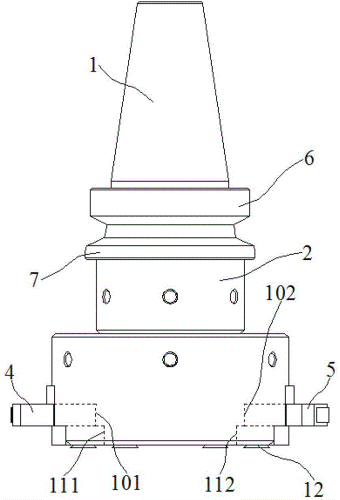
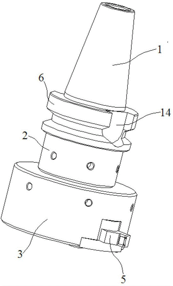
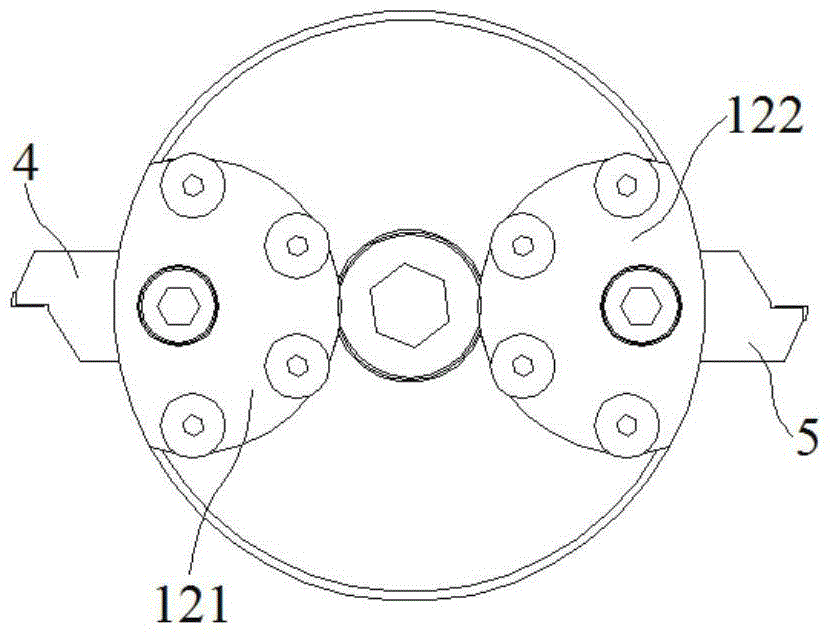
[0020] Embodiment 1: a kind of MCD arc milling cutter, comprises cutter shaft 1, connecting shaft 2, cutter head 3 and left and right diamond cutters 4,5, and the section of described cutter shaft 1 along its axis is a tapered surface, so The connecting shaft 2 is located between the cutter shaft 1 and the cutter head 3, the connection between the lower end of the connecting shaft 2 and the cutter shaft 1 is provided with a first flange 6 along the circumference, and the middle part of the connecting shaft 2 has a second flange 7. The left and right diamond knives 4 and 5 are all composed of a handle 8 and a diamond knives 9. The front portion of the protruding side diamond 9 has a diamond blade 91, and the connecting shaft 2 has 2 along the circumferential side. a positioning groove 14, and two positioning grooves 14 are symmetrically arranged on the side of the connecting shaft 2;

[0021] The cutter head 3 is provided with left and right mounting grooves 101, 102 and left a...

Embodiment 2

[0024] Embodiment 2: a kind of MCD arc milling cutter, comprises cutter shaft 1, connecting shaft 2, cutter head 3 and left and right diamond cutter 4,5, and the section of described cutter shaft 1 along its axis is a tapered surface, so The connecting shaft 2 is located between the cutter shaft 1 and the cutter head 3, the connection between the lower end of the connecting shaft 2 and the cutter shaft 1 is provided with a first flange 6 along the circumference, and the middle part of the connecting shaft 2 has a second flange 7. The left and right diamond cutters 4 and 5 are all composed of a handle 8 and a diamond cutter head 9. The diamond cutter head 9 on the protruding side has a diamond blade 91 at the front, and the connecting shaft 2 has 2 along the circumferential side. a positioning groove 14, and two positioning grooves 14 are symmetrically arranged on the side of the connecting shaft 2;

[0025] The cutter head 3 is provided with left and right mounting grooves 101...


PUM


Abstract

The invention discloses an MCD arc-surface-milling cutter. The MCD arc-surface-milling cutter comprises a cutter shaft, a connecting shaft, a cutter disc, a left diamond cutter and a right diamond cutter, wherein the section of the cutter shaft along the axis is a cone-shaped surface; the connecting shaft is located between the cutter shaft and the cutter disc, a first flange is arranged at the joint between the lower end of the connecting shaft and the cutter shaft along the circumferential direction, and a second flange is arranged in the middle of the connecting shaft; the left diamond cutter and the right diamond cutter consist of cutter handles and diamond cutter heads; diamond cutting edges are arranged at the front parts of the diamond cutter heads protruding out of the side surface; a left mounting groove, a right mounting groove, a left fixing groove and a right fixing groove are circumferentially formed in the cutter disc, the left mounting groove and the right mounting groove are formed right above the left fixing groove and the right fixing groove, respectively, the left diamond cutter and the right diamond cutter are embedded into the left mounting groove and the right mounting groove, respectively, and a left fixed block and a right fixed block are mounted in the left fixing groove and the right fixing groove through fixing bolts and clamp the left diamond cutter and the right diamond cutter; two positioning grooves are symmetrically formed in the side surface of the connecting shaft along the circumferential direction. According to the MCD arc-surface-milling cutter, a cut surface is relatively smooth and flat, a vertical line is eliminated, and problems that the cutter heads play or jump in a high-speed rotation process, the machining error is produced, and the machining precision is low are prevented.

Description

technical field [0001] The invention relates to the field of high-gloss cutters, in particular to an MCD arc milling cutter. Background technique [0002] Diamond has the advantages of extremely high hardness and wear resistance, low friction coefficient, high elastic modulus, high thermal conductivity, low thermal expansion coefficient and low affinity with non-ferrous metals; it can be used for non-metallic hard and brittle materials such as graphite, high wear resistance Precision machining of materials, composite materials, high-silicon aluminum alloys and other tough non-ferrous metal materials; in recent years, with the development trend of the national machinery field, the demand for diamonds is increasing. [0003] The existing metal parts for IT electronic products adopt surface polishing process, the main process: rough polishing plus fine polishing; equipment used: fanuc robot; material: polishing cloth wheel; process: rough polishing uses #500 cloth wheel on the ...

Claims


Application Information

Patent Timeline
Patent Type & Authority Applications(China)
IPC IPC(8): B23C5/20B23C5/22
CPCB23C5/20B23C5/2204
Inventor 徐金根宋帅佳
Owner KUNSHAN KERSEN SCI & TECH
Why Eureka
Try Eureka