Combined blade root
A combined, bladed technology that is applied to blade support elements, engine elements, machines/engines, etc. to increase flexibility, adjust quickly and easily, and avoid amplitude
- Summary
- Abstract
- Description
- Claims
- Application Information
AI Technical Summary
Problems solved by technology
Method used
Image
Examples
Embodiment 1
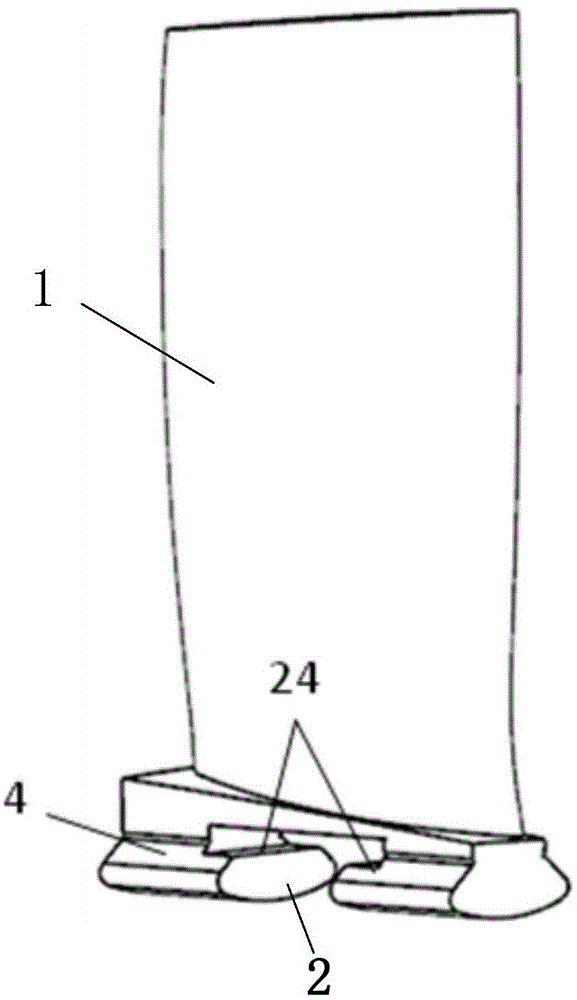
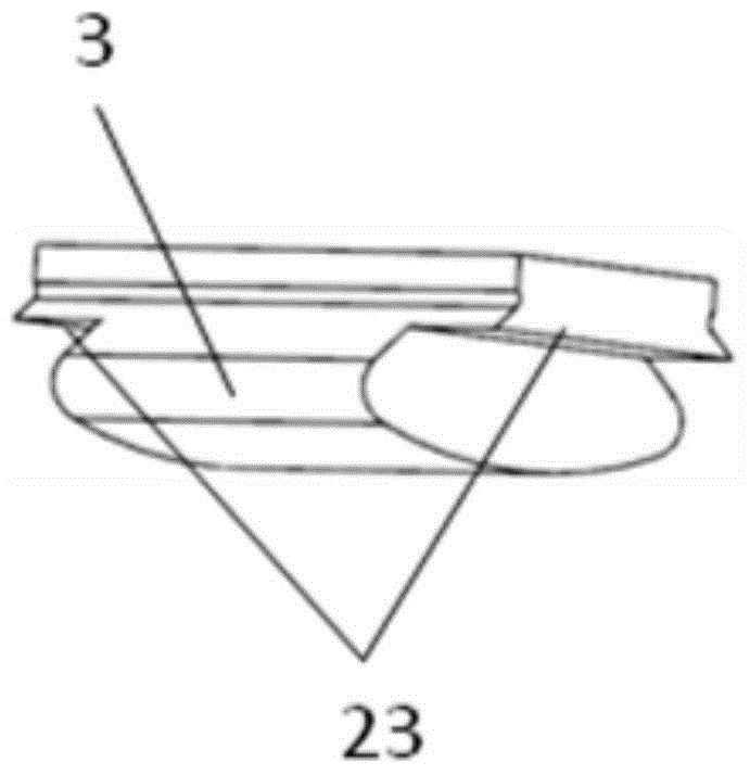
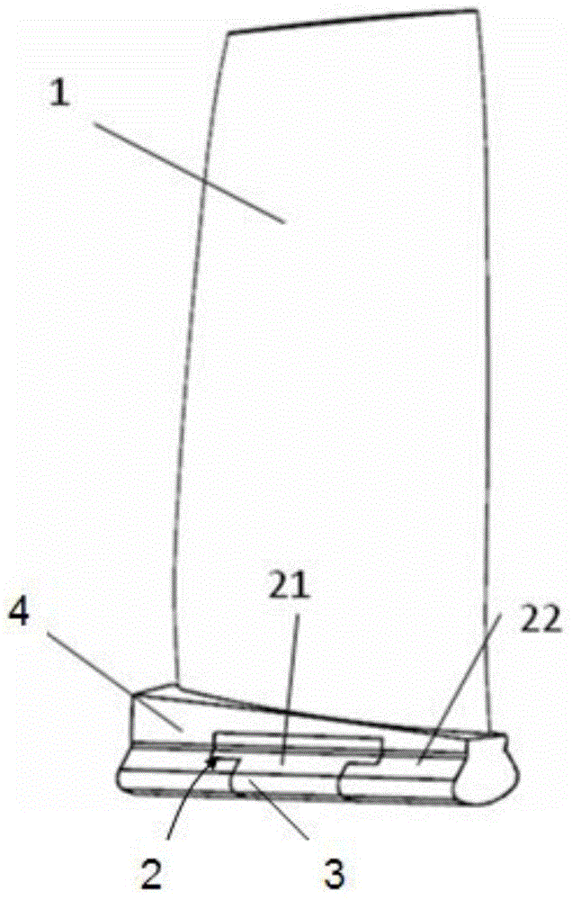
[0039] combine Figure 1 to Figure 3 As shown, a combined blade root provided by Embodiment 1 of the present invention includes a fixed block 4 and a movable block 3, the top of the fixed block 4 is used to fix the blade body; the lower part of the fixed block 4 has two radial sides The protruding first installation part and the slot 2 opened on the first installation part, the first installation part is used to engage with the wheel through the first working surface 21 on both radial sides; The movable block 3 is movably inserted in the slot 2, and the movable block 3 can be a variety of different elastic moduli, and the movable block 3 with an appropriate elastic modulus is selected according to the frequency-down or frequency-up requirements; the shaft of the fixed block 4 There is a gap between the two sides and the inner wall of the slot 2, and the lower part of the movable block 3 has a second installation part protruding to the two radial sides, and the second installat...
Embodiment 2
[0046] combine Figure 4 to Figure 6 As shown, a combined blade root provided in Embodiment 2 is basically the same in structure as Embodiment 1, and the similarities will not be described in detail. The difference lies in:
[0047] The second working surface 22 is provided with a concave cutting surface than the first working surface 21, and the vibration-damping material 25 is filled in the cutting surface. The vibration-damping material 25 can be damping glue, and the vibration-damping material 25 can also absorb vibration energy to a certain extent, and further realize the adjustment of vibration frequency.
Embodiment 3
[0049] combine Figure 7 to Figure 9 As shown, the combined blade root provided in the third embodiment has basically the same structure as that in the second embodiment, and the similarities will not be repeated, but the difference is:
[0050]The opposite sides of the slot 2 and the axial sides of the movable block 3 are in a gradually retracting structure from top to bottom, that is, the opposite sides of the fixed block 4 and the axial sides of the movable block 3 are in the shape of Inverted dovetail shape, the movable block 3 is installed in the slot 2 that also forms an inverted trapezoidal structure from top to bottom through the gradual retraction structure on both sides of the axial direction from top to bottom. The movable block 3 of the second installation part adjusts the height of the movable block 3 in the slot 2, and then realizes the adjustment of the gap between the two sides of the movable block 3 and the fixed block 4, thereby realizing the adjustment of th...
PUM
 Abstract
Description
Claims
Application Information
 - R&D
- Intellectual Property
- Life Sciences
- Materials
- Tech Scout
- Unparalleled Data Quality
- Higher Quality Content
- 60% Fewer Hallucinations
Browse by: Latest US Patents, China's latest patents, Technical Efficacy Thesaurus, Application Domain, Technology Topic, Popular Technical Reports.
© 2025 PatSnap. All rights reserved.Legal|Privacy policy|Modern Slavery Act Transparency Statement|Sitemap|About US| Contact US: help@patsnap.com


