Eureka AIR delivers breakthrough ideas for toughest innovation challenges, trusted by R&D personnel around the world.

A compact type fully hydraulic walking pile-up valve

A fully hydraulic and integrated valve technology, applied in fluid pressure actuation devices, fluid pressure actuation system safety, servo motor components, etc., can solve problems such as excavator or loader safety hazards, large oil noise, and large impact , to avoid the problem of oil suction, avoid pressure shock, and achieve the effect of smooth parking process

Active Publication Date: 2015-09-16
浙江宏盛精密机械有限公司
View PDF6 Cites 7 Cited by
  • Summary
  • Abstract
  • Description
  • Claims
  • Application Information

AI Technical Summary

Problems solved by technology

Due to its disadvantages such as high energy consumption and poor controllability, manufacturers at home and abroad are looking for a way to start and stop softly, save energy, and have good controllability. The mode in which the motor drives the tires through the drive axle
However, in actual operation, due to the absence of a suitable control integrated valve, there are the following problems in the full hydraulic travel: 1. During the parking process of the equipment, the hydraulic system and the mechanical braking system are completely separated, resulting in poor parking stability of the equipment
2. During the braking (stopping) process, the impact is large, the oil is sucked and the noise is large
The above existing problems will not only affect the performance and life of the product itself, but also leave a great safety hazard for excavators or loaders, resulting in the development of current full hydraulic wheel excavators and loaders. Large impact, even lead to the failure of full hydraulic travel

Method used


Image

  • A compact type fully hydraulic walking pile-up valve
  • A compact type fully hydraulic walking pile-up valve
  • A compact type fully hydraulic walking pile-up valve

Examples


Embodiment Construction

[0029] Embodiments of the present invention will be further described in detail below in conjunction with the accompanying drawings.

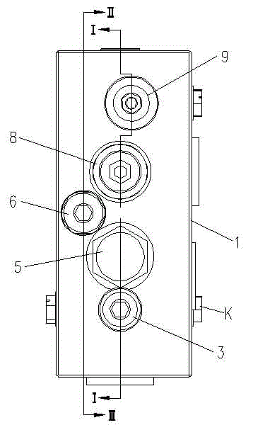
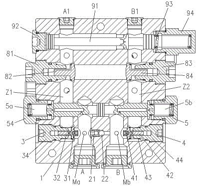
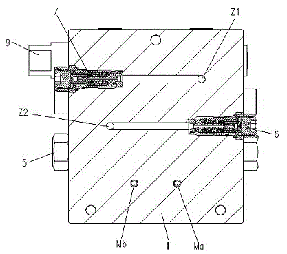
[0030] Figure 1 to Figure 8 It is a structural schematic diagram of the present invention.

[0031] The reference signs are: A port, B port, A1 port, B1 port, C port, T port, K ​​port, Ma port, Mb port, MU port, first main oil passage Z1, second main oil passage Z2 , valve body 1, high-pressure selector valve 2, third damper 2a, threaded check valve seat 21, steel ball 22, first one-way throttle valve 3, first detachable damper 31, first one-way throttle valve Core 32, first one-way throttle valve spring 33, first one-way throttle valve seat 34, second one-way throttle valve 4, second detachable damper 41, second one-way throttle valve core 42, first one-way throttle valve Second one-way throttle valve spring 43, second one-way throttle valve seat 44, balance valve 5, left pilot oil chamber 5a, right pilot oil chamber 5b, first damper 5c, fi...


PUM


Abstract

The invention provides a compact type fully hydraulic walking pile-up valve comprising a valve body. The valve body is internally provided with a high pressure selector valve formed by combining a threaded check valve base, a steel ball and a valve hole in the valve body. A first one-way throttle valve is arranged in the valve body and on the left side of the high pressure selector valve and a second one-way throttle valve is arranged in the valve body and on the right side of the high pressure selector valve. A balance valve is installed in a balance valve cavity of the valve body. A two-stage buffer overload valve comprising a first buffer overload valve and a second buffer overload valve is arranged on a main oil way in the valve body. A large-opening diameter oil supplementing valve formed by combining two sets of planar large-drift diameter check valves is installed in a valve cavity in the valve body and above the balance valve. An oil path switching valve is installed in the uppermost switching valve cavity of the valve body. The compact type fully hydraulic walking pile-up valve can effectively solve the problems such as great hydraulic shock, air suction of oil liquid and high noise in a braking process of fully hydraulic wheel excavators and loaders, has the advantages of compact structure, small size and high integration degree and is especially suitable for moving apparatuses.

Description

technical field [0001] The invention relates to the control technology of construction machinery full-hydraulic traveling mobile machinery, in particular to a control valve for full-hydraulic traveling wheeled excavators and loaders, specifically a compact full-hydraulic traveling integrated valve. Background technique [0002] At present, most of the wheeled excavators and loaders adopt the mechanical walking type, that is, the tires are directly driven by the diesel engine through the drive axle and gearbox. Due to its shortcomings such as high energy consumption and poor controllability, manufacturers at home and abroad are looking for a way to start and stop softly, save energy, and have good controllability. The motor drives the tires through the transaxle. However, in actual operation, due to the absence of a suitable control integrated valve, there are the following problems in the full hydraulic travel: 1. During the parking process of the equipment, the hydraulic s...

Claims


Application Information

Patent Timeline
Patent Type & Authority Applications(China)
IPC IPC(8): F15B13/02F15B20/00
CPCF15B13/02F15B20/00
Inventor 胡康梁
Owner 浙江宏盛精密机械有限公司
Why Eureka
Eureka Blog
Learn More