Real-time control system for traffic signal lamps at crossroad
A technology of real-time control system and traffic signal lights, which is applied to control the direction of traffic signals and other directions to achieve the effect of eliminating external interference.
- Summary
- Abstract
- Description
- Claims
- Application Information
AI Technical Summary
Problems solved by technology
Method used
Image

Examples
Embodiment Construction
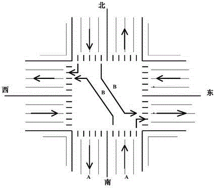
[0017] The traffic flow direction distribution diagram of the intersection traffic signal light real-time control system is as follows figure 1 As shown, the traffic flow distribution diagram at the intersection only shows one of various types of traffic flow distribution and its traffic flow control, and the real-time control system of traffic signal lights at intersections for other types of vehicle flow distribution and traffic flow control can be easily obtained by analogy. figure 1 In the middle, when the red light is on in the east-west direction, in the north-south direction, A is the time when the green light is on for the straight-through and right turn, and B is the time for the green light for the left turn to be on
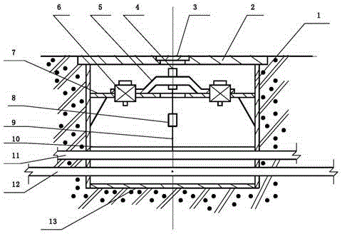
[0018] The schematic diagram of embedding the laser diode is as follows figure 2 shown. Its structure includes: steel pipe (1), cover plate (2), round glass sheet (3), laser diode kit (4), fixing plate (5), screw kit (6), bracket (7), junction box ( ...
PUM
 Abstract
Description
Claims
Application Information
PatSnap Eureka turns technology decisions into work you can execute. Powered by our Innovation Knowledge Graph, it runs expert workflows across engineering, life sciences, materials and intellectual property. Get your review-ready output in minutes.


