Method and device for testing quality factor of transmission coil in high-frequency wireless power transmission system
A technology for transmitting coils and quality factors, applied in the direction of measuring devices, measuring electricity, measuring electrical variables, etc., can solve the problems of inability to accurately test the internal resistance of the coil, calculate the coil, etc., and achieve the effect of eliminating external interference, accurate results, and accurate methods.
- Summary
- Abstract
- Description
- Claims
- Application Information
AI Technical Summary
Problems solved by technology
Method used
Image

Examples
Embodiment 1
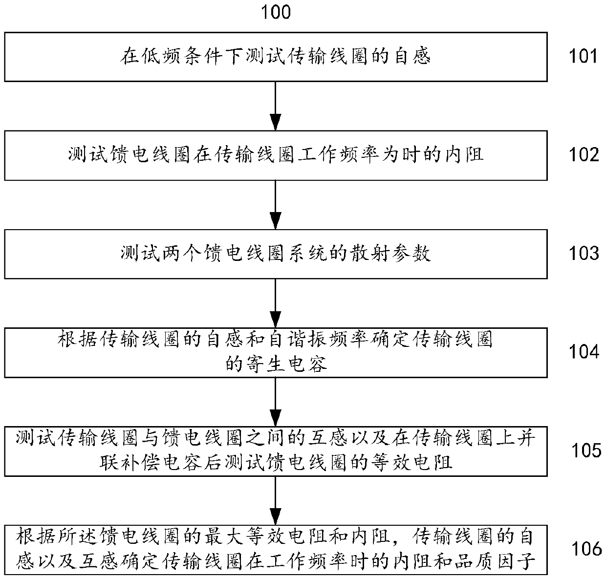
[0048] figure 1 It is a flowchart of a method for testing the quality factor of a transmission coil in a high-frequency wireless power transmission system according to a preferred embodiment of the present invention. Such as figure 1 As shown, the method 100 for testing the quality factor of a transmission coil in a high-frequency wireless power transmission system described in this preferred embodiment starts from step 101 .
[0049] In step 101, the self-inductance L of the transmission coil is tested under low frequency conditions;
[0050] In step 102, test the feeding coil at the transmission coil operating frequency f 0 When the internal resistance R ', wherein, the size of the feeding coil is not greater than the transmission coil, the number of turns is less than the number of turns of the transmission coil;
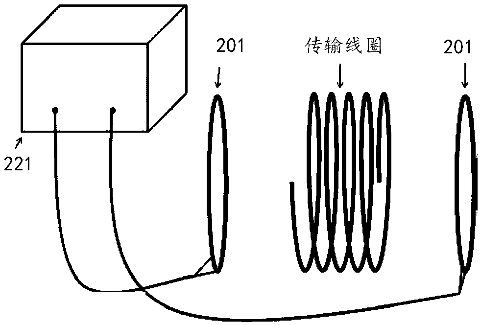
[0051] In step 103, the transmission coil is placed in the middle of two identical and coaxial feed coils, the scattering parameters of the two feed coil syst...
Embodiment 2
[0086] In this preferred embodiment, the copper wire with a wire diameter of 4mm is used to make a circular spiral transmission coil with 5 turns, a line spacing of 1cm, and a radius of 10cm. It needs to be tested at the operating frequency f 0 = Quality factor at 5MHz.
[0087] In step 1, the self-inductance of the transmission coil is L=20uH when the frequency is 1KHz tested by an impedance analyzer.
[0088] In step 2, use a copper wire with a wire diameter of 4mm to wind two identical feed coils with a radius of 10cm and a copper wire with a diameter of 4mm, and directly test its operating frequency f with an impedance analyzer. 0 When =5MHz, the internal resistance is R'=0.2Ω.
[0089]In step 3, place the circular helical transmission coil in the middle of the two coaxial feed coils, use the network analyzer to test the scattering parameters of the two feed coil systems, let the frequency 20MHz corresponding to the maximum value of the scattering parameters be the freque...
Embodiment 3
[0096] In this preferred embodiment, a copper wire with a wire diameter of 8 mm is used to make a square spiral transmission coil with 8 turns, a line spacing of 1 cm, and a radius of 20 cm. It needs to be tested at the operating frequency f 0 = Quality factor at 2MHz.
[0097] In step 1, when the testing frequency is 5KHz using an impedance analyzer, the self-inductance of the transmission coil is L=50uH.
[0098] In step 2, use a copper wire with a wire diameter of 8 mm to wind two identical feed coils with one turn and a radius of 20 cm. Directly test its working frequency f by impedance analyzer 0 When = 2MHz, the internal resistance is R' = 0.3Ω.
[0099] In step 3, place the square helical transmission coil in the middle of the two coaxial feed coils, use the network analyzer to test the scattering parameters of the two feed coil systems, let the frequency 8MHz corresponding to the maximum value of the scattering parameters be the transmission coil Resonant frequency ...
PUM
 Abstract
Description
Claims
Application Information