Servo motor and oil cylinder compound stamping mechanism and stamping method

A technology of servo motor and punching mechanism, applied in the field of punching mechanism, can solve the problems of high power of servo motor, long punching time, low punching efficiency, etc., and achieve the effect of saving punching time, low power and improving work efficiency

Active Publication Date: 2017-03-01
QINGDAO DONGHE TECH
View PDF6 Cites 0 Cited by
  • Summary
  • Abstract
  • Description
  • Claims
  • Application Information

AI Technical Summary

Problems solved by technology

At present, more and more CNC punching machines adopt mechanical type and servo main drive type, but there are still problems such as high power of servo motor, large stroke, long stamping time, low stamping efficiency, and cumbersome operation after truck processing.

Method used


Image

  • Servo motor and oil cylinder compound stamping mechanism and stamping method
  • Servo motor and oil cylinder compound stamping mechanism and stamping method
  • Servo motor and oil cylinder compound stamping mechanism and stamping method

Examples


Embodiment Construction

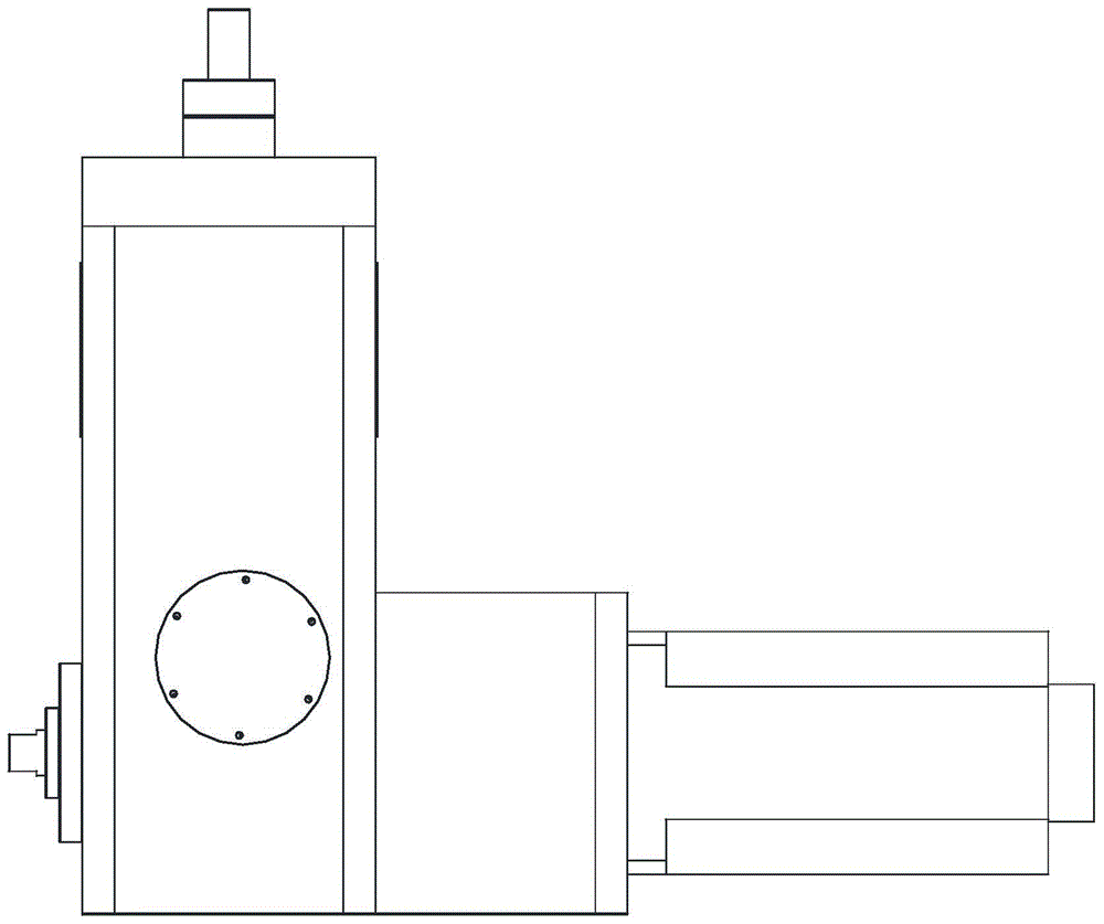
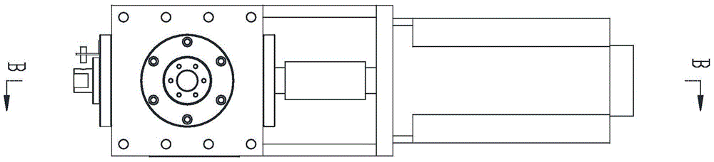
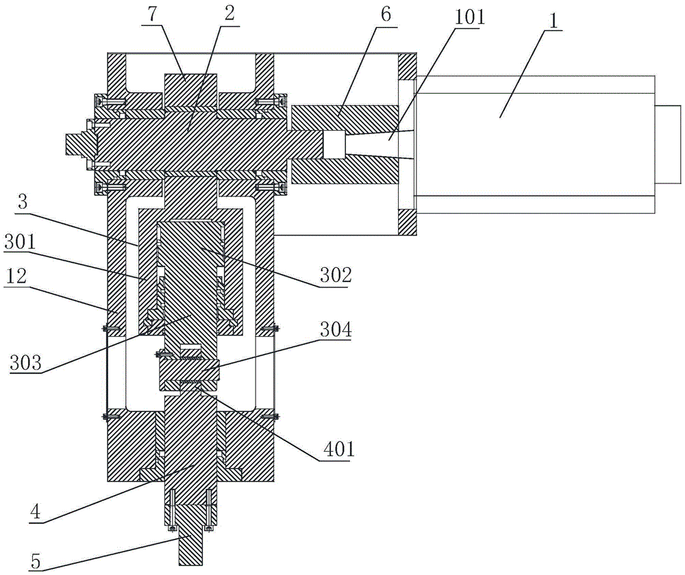
[0025] With reference to the drawings, a composite stamping mechanism with a servo motor and an oil cylinder includes a servo motor 1, a crankshaft 2, an oil cylinder 3, a sliding rod 4 and a striking head 5. The rotating shaft 101 of the servo motor 1 is drivingly connected to the crankshaft 2 through a coupling 6. The oil cylinder 3 includes a cylinder body 301, a piston 302 and a piston rod 303. The top end of the cylinder body 301 is provided with a lifting ring 7 which is sleeved on the crankshaft 2. The servo motor 1 drives the crankshaft 2 to run, and the crankshaft 2 drives the oil cylinder 3 to reciprocate up and down during the rotation. The piston 302 is arranged in the cylinder 301, the top end of the piston rod 303 and the piston 302 are fixedly connected, the bottom end of the piston rod 303 is movably connected with the top end of the sliding rod 4, and the bottom end of the sliding rod 4 is fixedly connected with the striking head 5. The cylinder 301 is connect...


PUM


Abstract

The invention discloses a servo motor and oil cylinder combined type stamping mechanism. The servo motor and oil cylinder combined type stamping mechanism comprises a servo motor, a crank shaft, an oil cylinder, a slide rod and a hitting head, wherein a rotary shaft of the servo motor is in driving connection with the crank shaft through a coupler, the oil cylinder comprises a cylinder body, a piston and a piston rod, the cylinder body is connected with the crank shaft, the servo motor drives the crank shaft to run, the crank shaft drives the oil cylinder to perform vertical reciprocating motion in the rotating process, the top end of the piston rod is connected with the piston, the bottom end of the piston rod is connected with the top end of the slide rod, the bottom end of the slide rod is connected with the hitting head, the cylinder body is externally connected with an oil way for controlling the vertical reciprocating motion of the oil cylinder, and the piston rod drives the hitting head to perform vertical actions through the slide rod. The servo motor and oil cylinder combined type stamping mechanism adopts the mode that the servo motor drives the oil cylinder to perform vertical reciprocating motion through the crank shaft and further drives the hitting head to hit a stamping die, the stroke of the crank shaft is effectively shortened, stamping time is saved, working efficiency is improved, and the servo motor is low in power, economical and capable of saving energy.

Description

Technical field [0001] The invention relates to a numerically controlled punching machine, in particular to a punching mechanism and a punching method for punching a punching die in the numerically controlled punching machine to complete a punching action. Background technique [0002] The CNC punching machine is an industrial processing equipment for punching and shallow drawing on the plate. It uses software programming to process the processing program. The plate is sent to the processing station through the feeding mechanism. At the same time, the system is in the mold library Select the appropriate processing die, and then press the programmed program through the stamping mechanism to complete the processing of the plate. The punching die in the CNC turret punch press is placed on the turntable, and the turntable is driven to rotate by the sprocket. When the turntable rotates to the corresponding punching station, the punch of the machine tool hits the punching die to comple...

Claims


Application Information

Patent Timeline
Patent Type & Authority Patents(China)
IPC IPC(8): B21D28/26B21D22/02
CPCB21D22/20B21D28/26
Inventor 陈克伟云立刚杨呈肖丽华
Owner QINGDAO DONGHE TECH
Why Eureka
Try Eureka