Method for improving precision of stepped components in laser spot-changing direct formation mode

A laser spot and laser technology, which is applied in the field of forming accuracy of wide components, can solve the problems of inconsistent growth height of the cladding layer, and achieve the effect of ensuring the forming quality and improving the forming accuracy

Active Publication Date: 2015-09-23
KUSN BAOJIN LASER TAILOR WELDED
View PDF5 Cites 27 Cited by
  • Summary
  • Abstract
  • Description
  • Claims
  • Application Information

AI Technical Summary

Problems solved by technology

[0007] The purpose of the present invention is to provide a method for improving the precision of laser variable spot direct forming of unequal width components, to solve the problem of inconsistency in the growth height of the cladding layer as the accumulation layer increases during the laser variable spot direct forming process, thereby improving the forming accuracy, Guaranteed forming quality

Method used


Image

  • Method for improving precision of stepped components in laser spot-changing direct formation mode
  • Method for improving precision of stepped components in laser spot-changing direct formation mode
  • Method for improving precision of stepped components in laser spot-changing direct formation mode

Examples


Embodiment 1

[0030] Embodiment one: see attached Figure 4 As shown in , it is a schematic diagram of the working principle of laser variable spot shaping. Based on the direct shaping of laser variable spots, this embodiment provides a method for improving the precision of components with unequal widths, including the following steps:

[0031] (1) Establish a three-dimensional forming part model with a computer, and process the model hierarchically through software to obtain the contour level information of the part;

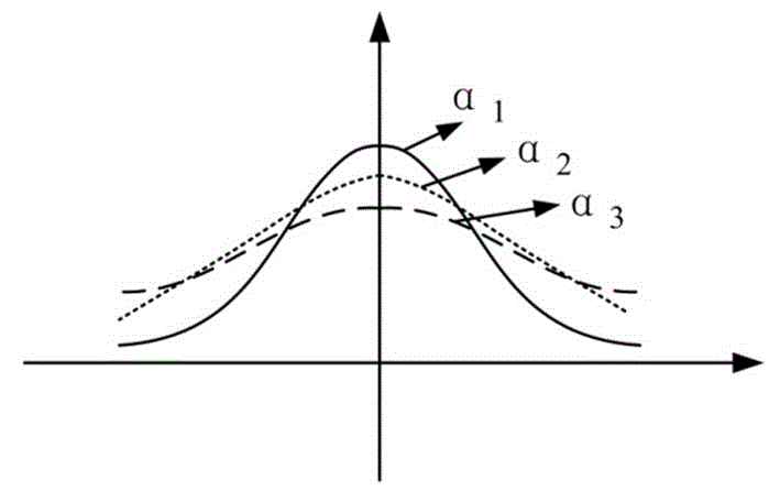
[0032] (2) See attached Figure 6 As shown, the driving device of the coaxial powder feeding nozzle is controlled, and the size of the laser spot is continuously adjusted in real time according to the size of the melting channel. During the process of laser spot change, the laser power, scanning speed and powder feeding amount are simultaneously adjusted for single-pass cladding. , measuring and obtaining the cross-sectional width and height data of a single cladding layer...


PUM


Abstract

The invention discloses a method for improving precision of stepped components in a laser spot-changing direct formation mode. The method includes the steps that a cladding test is performed firstly, the sectional width and height data of a single-track cladding layer under different technological parameters are obtained, orders of a sectional curve of the cladding layer under different aspect ratios are fitted out, and the function relationship between the orders of the sectional curve of the cladding layer under the different aspect ratios and the height and lifting capacity of the single-track cladding layer is built; then single step-shaped tracks corresponding to the same lifting capacity are built, the technological parameters of the laser spot-changing cladding single tracks are determined according to the single step-shaped tracks, and a highly-smooth cladding layer is formed in a cladding mode through laser spot-changing direct formation; after one cladding layer is completed, a spray nozzle is lifted by a layering height, new fusion tracks are formed in a cladding mode through the single step-shaped tracks, and operations circulate until manufacturing of a three-dimensional part is completed. By means of the method, the highly-smooth cladding layer is obtained, the phenomenon that the top of the cladding layer is not even and portions of small aspect ratios are prone to tension fracture is avoided, and the method improves formation precision and guarantees formation quality.

Description

technical field [0001] The invention relates to a laser direct forming method, in particular to a method for improving the forming accuracy of directly forming unequal-width components through laser variable spots. Background technique [0002] Laser metal direct forming technology is an advanced manufacturing technology developed on the basis of laser cladding and combined with rapid prototyping technology. Based on the "discrete-stack" forming principle, first establish the 3D CAD model of the processed parts, then divide the 3D model into a series of 2D planes, plan a reasonable laser scanning path according to the 2D plane outline, and then transform it into CNC work The operation instructions of the platform can finally realize the direct forming of metal parts. Compared with general rapid prototyping technology, laser metal direct forming technology can quickly manufacture complex metal parts that are difficult to manufacture by traditional methods; realize the manufa...

Claims


Application Information

Patent Timeline
Patent Type & Authority Applications(China)
IPC IPC(8): B22F3/105B33Y10/00B33Y50/02
CPCY02P10/25
Inventor 朱刚贤陆斌石世宏傅戈雁吴继琸
Owner KUSN BAOJIN LASER TAILOR WELDED
Why Eureka
Try Eureka