
Automobile shock absorber

A technology for automobile shock absorbers and vehicles, applied in shock absorbers, springs/shock absorbers, shock absorbers, etc., can solve the problem of short service life, poor shock absorption effect, and easy failure of shock absorber rebound ability. problems, to achieve the effect of simplifying the structure, facilitating maintenance, and reducing hydraulic components

Inactive Publication Date: 2017-05-24
窦贵昊
View PDF10 Cites 3 Cited by
  • Summary
  • Abstract
  • Description
  • Claims
  • Application Information

AI Technical Summary

Problems solved by technology

[0009] CN105370790A discloses an automobile shock absorber, which includes: a support plate, a piston rod, a piston, a cylinder, a first return spring and a permanent magnet, and the support plate, piston rod and piston are from top to bottom In sequence, the permanent magnet is arranged on the top of the cylinder body and is fixedly connected with the cylinder body, the piston is arranged in the cylinder body, the support plate is arranged above the upper surface of the cylinder body, and the piston rod The upper end passes through the upper part of the cylinder, the first return spring is sleeved on the piston rod, and one end is connected to the support plate, and the other end is fixed on the top of the cylinder, which overcomes the reduction in the prior art. After a long-term use of the shock absorber, the shock absorption effect will become worse, the rebound ability of the shock absorber will easily fail, and the service life will be short, so as to provide a long-term shock absorber with good shock absorption effect during long-term use, and the shock absorber rebounds Strong elastic capacity and long service life automobile shock absorber

Method used


Image

  • Automobile shock absorber
  • Automobile shock absorber
  • Automobile shock absorber

Examples


preparation example 1

[0062]S1: Weigh 108 parts by mass of three-component composite elastic base material (composed of 100 parts by mass of nitrile rubber, 5 parts by mass of styrene-based thermoplastic elastomer (TPES) and 3 parts by mass of polyamide-based thermoplastic elastomer (TPAE) ), 1 part by mass of SiC whiskers with a length of 0.1-0.2mm, 2 parts by mass of dilaurate thiodipropionate, 0.1 part by mass of di-n-butyltin dilaurate, 0.3 parts by mass of ethylene-vinyl acetate copolymer ( EVA), 0.6 parts by mass of methacryloxypropyltrimethoxysilane, 1.2 parts by mass of 4,4'-diaminobicyclohexylmethane and 2 parts by mass of silicon dioxide powder with a particle size of 50-100nm;

[0063] S2: Add SiC whiskers, dilaurate thiodipropionate, ethylene-vinyl acetate copolymer (EVA), and methacryloxypropane with a total amount of 20% to the three-component composite elastic base material. Trimethoxysilane (0.12 parts by mass) and 4,4'-diaminobicyclohexylmethane (0.96 parts by mass) in a total amou...

preparation example 2

[0066] S1: Weigh 112 parts by mass of three-component composite elastic base material (composed of 100 parts by mass of nitrile rubber, 10 parts by mass of styrene thermoplastic elastomer (TPES) and 2 mass parts of polyamide thermoplastic elastomer (TPAE) ), 2 parts by mass of SiC whiskers with a length of 0.1-0.2mm, 1 part by mass of dilaurate thiodipropionate, 0.3 parts by mass of di-n-butyltin dilaurate, 0.2 parts by mass of ethylene-vinyl acetate copolymer ( EVA), 0.9 parts by mass of methacryloxypropyltrimethoxysilane, 1 part by mass of 4,4'-diaminobicyclohexylmethane and 3 parts by mass of silicon dioxide powder with a particle size of 50-100nm;

[0067] S2: Add SiC whiskers, dilaurate thiodipropionate, ethylene-vinyl acetate copolymer (EVA), and methacryloxypropane in a total amount of 30% to the three-component composite elastic base material. Trimethoxysilane (0.27 parts by mass) and 4,4'-diaminobicyclohexylmethane (0.7 parts by mass) in a total amount of 70%, and the...

preparation example 3

[0070] S1: Weigh 110 parts by mass of three-component composite elastic base material (composed of 100 parts by mass of nitrile rubber, 7.5 parts by mass of styrene-based thermoplastic elastomer (TPES) and 2.5 parts by mass of polyamide-based thermoplastic elastomer (TPAE) ), 1.5 parts by mass of SiC whiskers with a length of 0.1-0.2mm, 1.5 parts by mass of dilaurate thiodipropionate, 0.2 parts by mass of di-n-butyltin dilaurate, 0.25 parts by mass of ethylene-vinyl acetate copolymer ( EVA), 0.8 parts by mass of methacryloxypropyltrimethoxysilane, 1.1 parts by mass of 4,4'-diaminobicyclohexylmethane and 2.5 parts by mass of silicon dioxide powder with a particle size of 50-100nm;

[0071] S2: Add SiC whiskers, dilaurate thiodipropionate, ethylene-vinyl acetate copolymer (EVA), and methacryloxypropane in a total amount of 25% to the three-component composite elastic base material. Trimethoxysilane (0.2 parts by mass) and 4,4'-diaminobicyclohexylmethane (0.825 parts by mass) in ...


PUM


Abstract

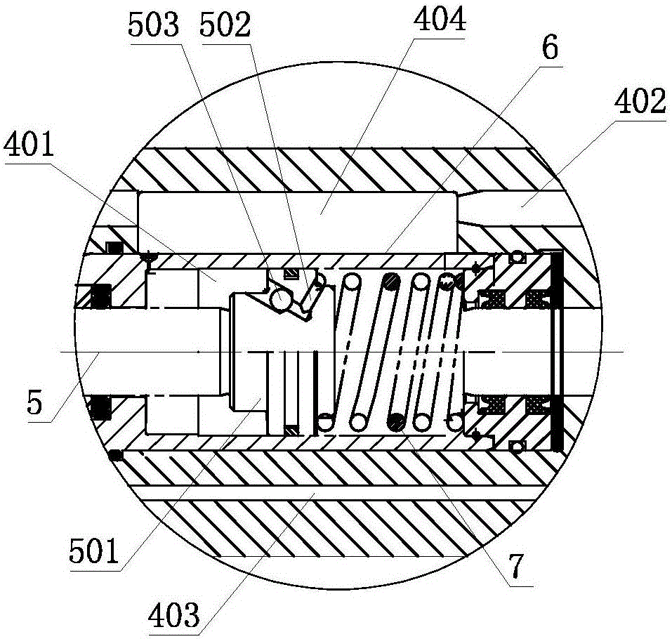
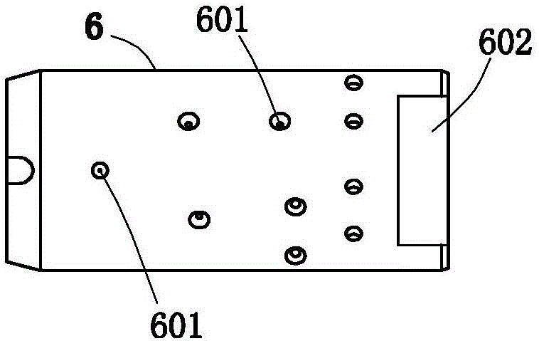
The invention discloses an automobile shock absorber. The automobile shock absorber comprises a buffer connected with an automobile adapter, wherein the buffer comprises a buffer housing; the buffer housing is provided with a piston cavity; a buffering piston shaft is mounted in the piston cavity in a sliding manner; a damping cylinder is arranged in the piston cavity; a reset spring is arranged in the damping cylinder; a lubricating oil inlet channel is formed in the buffer housing; an oil storage tank is formed in one side located on the lubricating oil inlet channel, of the buffer housing; a plurality of through holes are formed in the damping cylinder; the through holes communicate with the piston cavity and the oil storage tank; a lubricating oil discharging channel is formed in one side, away from the lubricating oil inlet channel, of the buffer housing; and damping channels which are respectively formed in two sides of the piston and communicate with the buffering piston shaft are arranged on the piston of the buffering piston shaft. According to the shock absorber disclosed by the invention, through unique structural design, multiple beneficial effects are archived, so that the shock absorber has good application prospects and latent industrial productive capacity in the automobile manufacturing field and the shock absorber field.

Description

technical field [0001] The invention relates to a shock absorber, more particularly to an automobile shock absorber, and belongs to the technical field of shock absorbers. Background technique [0002] In order to quickly attenuate the vibration of the frame and the body and improve the ride comfort and comfort of the car, the car suspension system is generally equipped with a shock absorber. The shock absorber is a vulnerable part during the use of the car. The shock absorber Whether it works well or not will directly affect the driving stability of the car and the life of other parts, so the shock absorber should always be in good working condition. [0003] The shock absorber is mainly used to suppress the shock when the spring rebounds after absorbing the shock and the impact from the road surface, and to counteract the torsional vibration of the crankshaft (that is, the phenomenon that the crankshaft is twisted by the impact force of the cylinder ignition). Vibration i...

Claims


Application Information

Patent Timeline
Patent Type & Authority Applications(China)
IPC IPC(8): F16F13/00F16F9/36F16F9/32F16F9/54C08L9/02C08L77/00C08K13/04C08K7/26C08K3/36
CPCF16F13/007C08K2201/003C08K2201/004C08L9/02C08L2201/08C08L2205/035C08L2207/04F16F9/3278F16F9/361F16F9/362F16F9/54F16F2224/025F16F2226/00C08L77/00C08K13/04C08K7/26C08K3/36
Inventor 窦贵昊马鹏程窦省委
Owner 窦贵昊
Learn More