Automatic quenching oil tank

A quenching oil tank, automatic technology, applied in the direction of quenching device, furnace type, furnace, etc., can solve the problems of unfavorable automatic quenching of leaf spring, strong mechanical plasticity, irregular arrangement position, etc., to reduce quenching labor intensity, improve quenching efficiency, The effect of improving quenching quality

Active Publication Date: 2015-09-23
山东森德数控机械有限公司
View PDF4 Cites 5 Cited by
  • Summary
  • Abstract
  • Description
  • Claims
  • Application Information

AI Technical Summary

Problems solved by technology

Because the leaf spring is in a high temperature state and has strong mechanical plasticity, it is easy to cause large deformation due to movement, and it will also have an adverse effect on the uniformity of quenching quality.
In addition, due to the up and down mo

Method used


Image

  • Automatic quenching oil tank
  • Automatic quenching oil tank
  • Automatic quenching oil tank

Examples


Example Embodiment

[0017] In order to facilitate the understanding of the technical content of the present invention, its technical solution will be further described below in conjunction with the accompanying drawings.
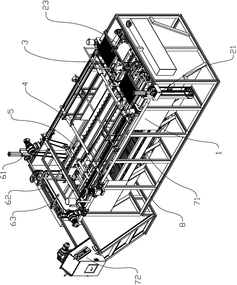
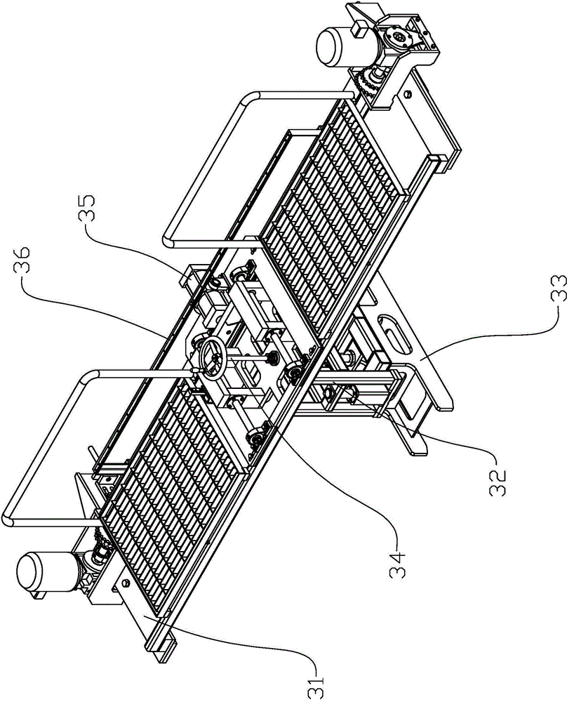
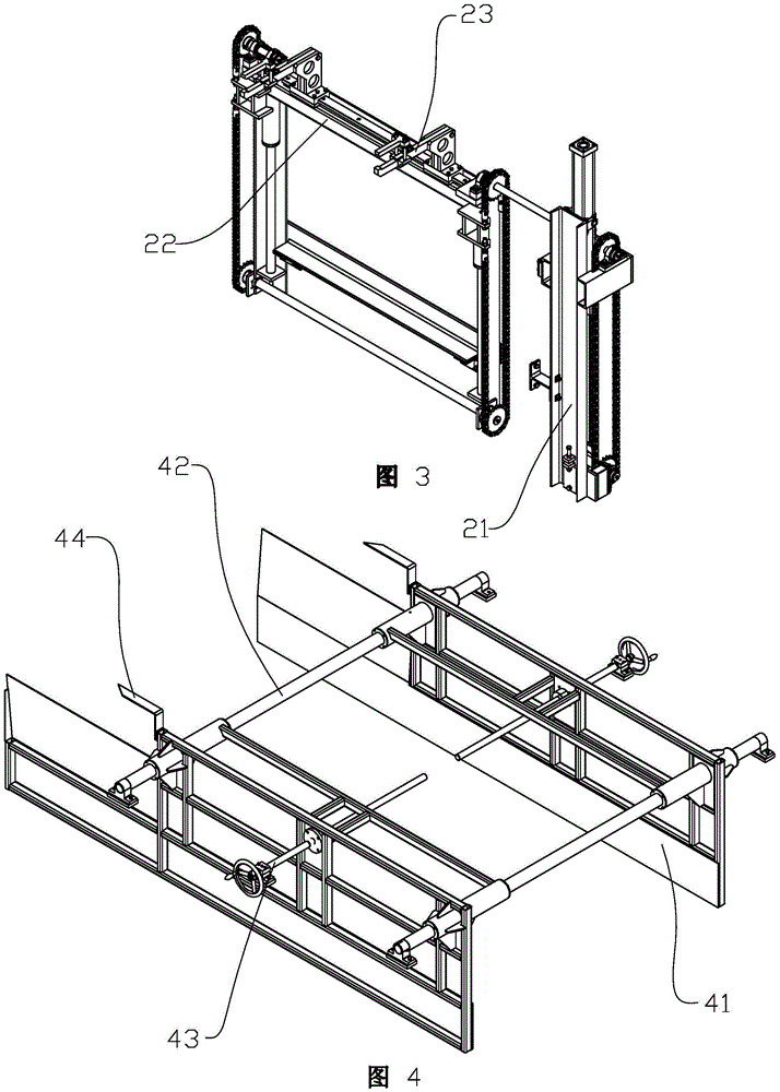
[0018] Such as Figure 1 to Figure 4 An automatic quenching oil tank shown includes a feeding device, a discharging device, a skid prevention machine 3, a stopper 4, a quenching conveyor chain 5, a slag scraper 71 placed under the quenching conveyor chain 5, and an oxide scale slag elevator 72 and forced circulation cooling system. The feeding device includes a feeding elevator 21, a feeding elevator 22, and a feeding manipulator 23. Similarly, the discharging device includes a feeding elevator 61, a discharging elevator 62, and a feeding manipulator 63, and the feeding, The elevator in the discharging device and the elevator frame have the same matching form, which is a structure that realizes the lifting drive through a sprocket and chain mechanism. There are two feeding manip...


PUM


Abstract

An automatic quenching oil tank comprises a feeding device, a discharging device, a quenching conveying chain and an antiskid machine. The antiskid machine comprises an antiskid rack, a vertical sliding seat and a cylinder fixed on the antiskid rack, chain rails are arranged on the left side and the right side of the upper end of an oil tank frame, the left end and the right end of the antiskid rack are matched with the left side and the right side of the oil tank frame through a sliding rail structure, a rotating shaft extending in left-right direction is arranged on the antiskid rack, chain wheels corresponding to the chain rails arranged on the oil tank frame are arranged on the rotating shaft, the rotating shaft is connected with a driving motor, a push rod of the cylinder is arranged in front-rear direction, the end of cylinder is connected with the vertical sliding seat, a vertical screw is arranged at the upper end of the vertical sliding seat, and a press plate is arranged at the lower end of the vertical screw and assembled at the lower end of the vertical sliding seat through a line rail which is arranged in a vertically-extending manner. By the automatic quenching oil tank, large deformation of a plate spring in the process of quenching can be prevented, quenching quality is improved, realization of automated quenching is facilitated, quenching efficiency is improved, and quenching labor intensity is reduced.

Description

technical field [0001] The invention relates to the related technical field of leaf spring production equipment, in particular to an automatic quenching oil tank. Background technique [0002] The existing leaf spring quenching oil tank includes feeding and discharging devices, a quenching conveying chain, a slag scraper placed under the quenching conveying chain, an oxide skin slag elevator and a forced circulation cooling system. During the production process, the leaf spring is placed at the feeding end of the quenching conveyor chain. Because there is no auxiliary mechanism to limit the position of the leaf spring, the boiling oil and the bubbles generated during quenching will exert force on the leaf spring. And make leaf spring move up and down and back and forth. Because the leaf spring is in a high temperature state and has strong mechanical plasticity, it is easy to cause large deformation due to movement, and it will also have an adverse effect on the uniformity o...

Claims


Application Information

Patent Timeline
IPC IPC(8): C21D1/63C21D9/02
CPCY02P10/20
Inventor 石学友王翔洲步砚杰付勇朱洪伟韩增颂陈启军李公哲
Owner 山东森德数控机械有限公司
Why Eureka
Try Eureka