
Energy-saving design method for variable-load servo control system

A technology of a servo control system and a design method, which is applied to servo meter circuits, servo motors, fluid pressure actuating system components, etc., can solve problems such as low energy utilization rate, achieve high energy utilization rate, high efficiency, and improve energy saving Effect

Active Publication Date: 2015-09-23
YANSHAN UNIV
View PDF11 Cites 10 Cited by
  • Summary
  • Abstract
  • Description
  • Claims
  • Application Information

AI Technical Summary

Problems solved by technology

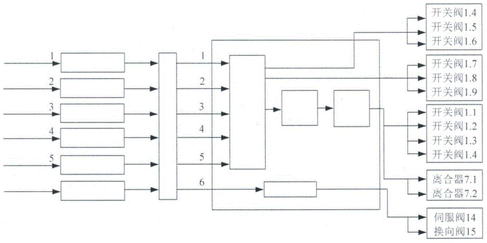
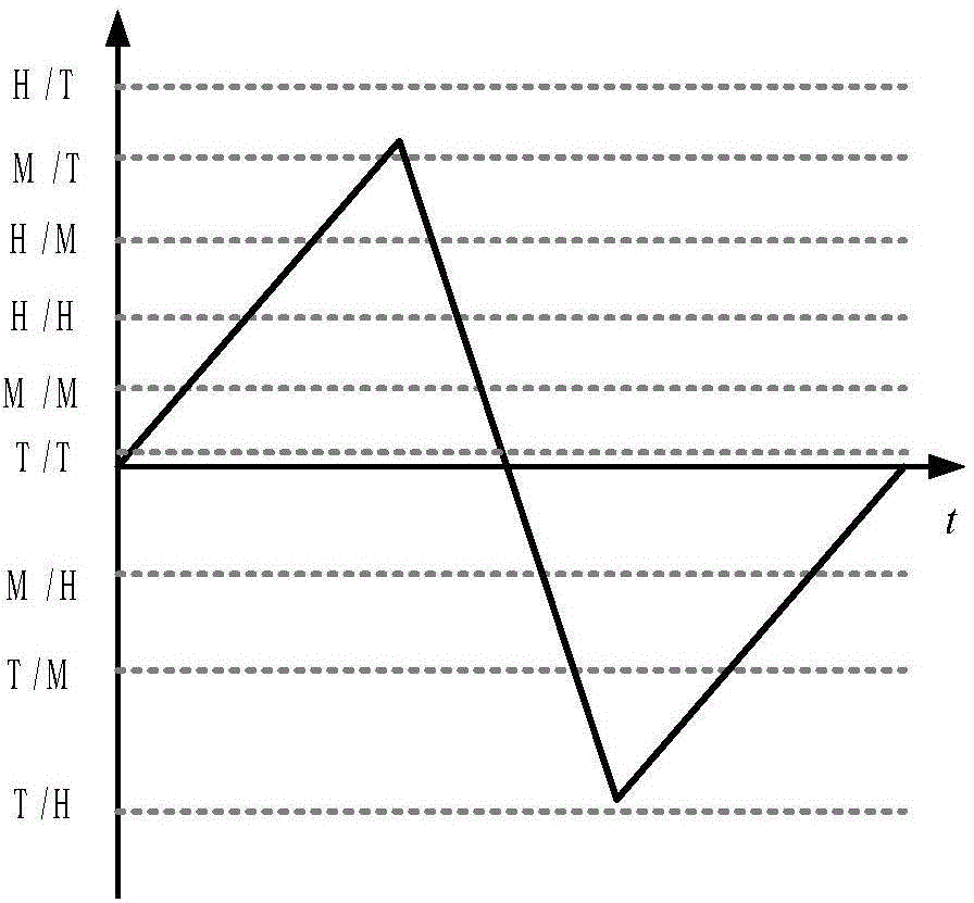
[0004] The purpose of the present invention is to provide an energy-saving design method for a variable load servo control system based on load force matching for the problem of low energy utilization in variable load hydraulic servo systems

Method used


Image

  • Energy-saving design method for variable-load servo control system
  • Energy-saving design method for variable-load servo control system
  • Energy-saving design method for variable-load servo control system

Examples


Embodiment Construction

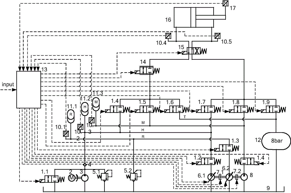
[0024] The variable load servo control energy-saving system is mainly composed of four oil circuits, which are energy storage oil circuit R and three high-pressure oil circuits H, medium-pressure oil circuit M, and low-pressure oil circuit T with different pressure levels. The quantitative pump 3 in the system is driven by the motor 2. The outlet of the quantitative pump is divided into three oil circuits, which are respectively connected with the oil inlet of the check valve 4, the safety valve 5.1 and the on-off valve 1; the oil outlet of the safety valve 5.1 and the on-off valve 1 It is directly connected to the fuel tank 9; the oil outlet of the check valve 4 is connected to the high-pressure oil circuit H, and the high-pressure oil circuit H is respectively connected to the high-pressure accumulator 11.2, the pressure sensor 10.2, the left and right double switch valves 1.4, 1.7 oil inlets, energy The on-off valve 1.2 of the transfer unit is connected to the oil inlet; the...


PUM


Abstract

The invention relates to an energy-saving design method for a variable-load servo control system. According to a hydraulic system designed through the design method, fitting of matched load force is achieved through arbitrary combination of different pressure grades, and throttling losses of a valve port are reduced. Overall management of energy is achieved by means of an energy transmission unit and an energy storage unit. Control is conducted according to the working condition, so that regeneration and recycling of energy are achieved. The transmission efficiency of the system is improved on the premise that the control characteristic is guaranteed.

Description

technical field [0001] The invention belongs to the application field of hydraulic technology, and relates to an energy-saving design method of a variable load servo control system. Background technique [0002] As an emerging science and technology developed after the 1950s and 1960s, hydraulic servo control is widely used in the defense industry, aviation It has gained important applications in aerospace, non-ferrous smelting, power engineering, vehicle engineering, petrochemical and other fields. However, in the traditional hydraulic transmission, due to a large number of pressure mismatches and flow mismatches, a large number of throttling losses and overflow losses are caused. This brings problems such as low transmission efficiency and high heat generation of the hydraulic servo system, resulting in serious energy waste and environmental pollution, and even affects the competitiveness and application range of hydraulic servo technology. Therefore, it is urgent to see...

Claims


Application Information

Patent Timeline
Patent Type & Authority Applications(China)
IPC IPC(8): F15B1/02F15B21/14F15B9/04
CPCF15B9/04F15B21/14F15B2211/205
Inventor 姚静李彬
Owner YANSHAN UNIV
Learn More