a dryer

A dryer and outer cylinder technology, which is applied in the field of dryers, can solve the problems that granular fertilizers are easily broken, easy to agglomerate, and the dryer cannot be fed uniformly, so as to reduce the impact force

Inactive Publication Date: 2017-05-03
贵州省瓮安兴农磷化工有限责任公司
View PDF7 Cites 0 Cited by
  • Summary
  • Abstract
  • Description
  • Claims
  • Application Information

AI Technical Summary

Problems solved by technology

[0003] Since the single-cylinder dryer is a general-purpose dryer, the wet granulated fertilizer to be dried after being balled into balls has high moisture content and low strength. When it enters the drying cylinder, due to the diameter of the dryer, If it is too large, the granular fertilizer with high moisture content will fall from the high end to the low end of the cylinder, and the granular fertilizer will be easily broken; from the front end to the rear end of the dryer cylinder, the fertilizer particles will fall repeatedly, which will easily cause the appearance of the fertilizer particles to be poor. Too much powder, low yield
The structure of the double cylinder dryer makes it impossible for the dryer to feed evenly. Most of the material enters between the outer cylinder and the inner cylinder, while the material in the inner cylinder is very small, so the double cylinder drying cannot be effectively used. The advantages of machine structure are used to dry granular fertilizers; granular fertilizers with different components contain different moisture after they are pelletized. For granular fertilizers with high moisture content, they are easy to agglomerate in the feeding port, which is not conducive to smooth feeding.

Method used


Image

  • a dryer
  • a dryer
  • a dryer

Examples


Embodiment Construction

[0012] The present invention will be further described below in conjunction with the accompanying drawings and embodiments, but not as a basis for limiting the present invention.

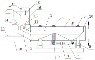
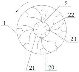
[0013] Example. a dryer such as Figure 1-3 As shown, it includes an outer cylinder body 1, an inner cylinder body 2 coaxial with the outer cylinder body 1 is provided, a feed housing 10 is provided at one end of the outer cylinder body 1, and an air inlet pipe 19 is provided inside the feed housing 10 , the two supporting rings 3 and the ring gear 4 on the wall of the outer cylinder 1, the ring gear 4 is arranged between the two supporting rings 3, and the matching supporting wheel 5 is correspondingly provided under the supporting ring 3, and the ring gear 4 A gear 6 is arranged below, and the gear 6 is meshed with the ring gear 4, and the motor 7 transmits the gear 6 through a transmission 8; a hopper 9 is arranged above the feeding housing 10, and a hygrometer 18 is arranged in the hopper 9; th...


PUM


Abstract

The invention discloses a drying machine which comprises an outer cylinder. An inner cylinder coaxial with the outer cylinder is arranged in the outer cylinder, a feeding shell is arranged at one end of the outer cylinder, a gas inlet pipe is arranged in the feeding shell, a hopper is arranged above the feeding shell, and a hygrometer is arranged in the hopper. A first feeding funnel and a second feeding funnel are arranged at a discharging opening of the hopper. A support is arranged on the feeding shell and connected with a vibration bar through a vibration motor, and the vibration bar stretches in the hopper. The inner wall of the outer cylinder and the inner wall of the inner cylinder are provided with hook-shaped lifting boards, the outer wall of the inner cylinder is connected with the inner wall of the outer cylinder through an arc support, and an arc lifting device is arranged on the outer wall of the inner cylinder. According to the drying machine, dried fertilizer particles are good in appearance, little in powder and high in yield, the feeding amount can be effectively scattered, and smooth feeding is facilitated.

Description

technical field [0001] The invention relates to a granular fertilizer production equipment, in particular to a dryer. Background technique [0002] At present, the traditional dryer is also called a single cylinder dryer because it has only one drying cylinder. The drying process is: the dry wet material is sent to the hopper by the belt conveyor or bucket elevator, and then enters the feeding end through the feeding pipe of the feeding machine of the hopper. The inclination of the feeding pipe should be greater than the natural inclination of the material so that the material can flow into the dryer smoothly. The drum of the dryer is a rotating drum that is slightly inclined to the horizontal line. The material is fed from the higher end, and the heat carrier enters from the lower end, and contacts with the material in countercurrent, and some heat carrier and material flow into the cylinder simultaneously. With the rotation of the cylinder, the material moves to the low...

Claims


Application Information

Patent Timeline
Patent Type & Authority Patents(China)
IPC IPC(8): F26B11/06F26B25/04F26B1/00F26B25/00
Inventor 陈远芳
Owner 贵州省瓮安兴农磷化工有限责任公司
Why Eureka
Try Eureka