An ultrasonic atomization sampling device

A sampling device, ultrasonic atomization technology, applied in measuring devices, material analysis through optical means, instruments, etc., can solve problems such as residues, achieve the effects of improving accuracy, reducing interference, and preventing non-directionality

Inactive Publication Date: 2018-01-16
ZHEJIANG UNIV
View PDF10 Cites 2 Cited by
  • Summary
  • Abstract
  • Description
  • Claims
  • Application Information

AI Technical Summary

Problems solved by technology

[0008] The invention provides an ultrasonic atomization sampling device which not only solves the problem of residual waste liquid, but also improves the atomization efficiency of the sample solution

Method used


Image

  • An ultrasonic atomization sampling device
  • An ultrasonic atomization sampling device
  • An ultrasonic atomization sampling device

Examples


Embodiment 1

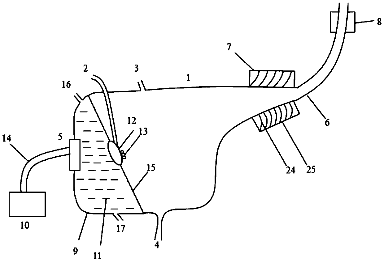
[0040] Such as figure 1 As shown, an ultrasonic atomization sampling device, the isolation glass 15 installed obliquely divides the cavity into a coupling chamber 9 and a spray chamber 1, and a resonant membrane 12 is installed in the center of the isolation glass 15 with an inclination of 60°.

[0041] An ultrasonic transducer 5 is installed on the side wall of the coupling chamber 9 , and the ultrasonic transducer 5 is electrically connected to the ultrasonic generating circuit 10 through a cable 14 . The interior of the coupling chamber 9 is filled with coupling water 11 , the upper part of the coupling chamber 9 communicates with the water inlet pipe 16 , and the lower part communicates with the water outlet pipe 17 .

[0042] The atomization chamber 1 has a fan-shaped structure of 30°. The upper part of the atomization chamber 1 extends into the sampling tube 2 , and the outlet of the sampling tube 2 is close to the resonant membrane 12 for transporting the sample solutio...

Embodiment 2

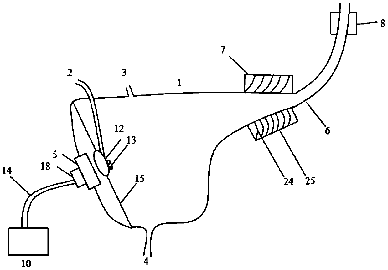
[0051] Such as image 3 As shown, an ultrasonic atomization sampling device differs from Embodiment 1 in that instead of using coupling water 11 and a circulating cooling system, the resonant membrane 12 is directly pasted on the surface of the ultrasonic transducer 5 to simplify coupling. The resonant film 12 is parallel to the ultrasonic transducer 5, and the inclination is set to 45° in this embodiment according to the required conditions. The resonant membrane 12 is close to the ultrasonic transducer 5 to ensure that the ultrasonic energy is directly coupled to the resonant membrane 12 through the air.

[0052] A cooling device 18 is installed on the surface of the ultrasonic transducer 5 for cooling the ultrasonic transducer 5 .

[0053] Such as Figure 4 As shown, the cooling device 18 includes a cooling fin 21 and a cooling plate 23, the cooling plate 23 is bonded to the ultrasonic transducer 5, and the cooling fin 21 is evenly inserted on the surface of the cooling p...


PUM


Abstract

The invention discloses an ultrasonic atomization device, which comprises a cavity separated into a coupling chamber and an atomization chamber by an insulating glass installed obliquely; an ultrasonic transducer controlled by an ultrasonic generating circuit is installed on the side wall of the coupling chamber; The upper part of the chemical chamber is connected with an air inlet pipe and a sample feeding pipe, and the lower part is connected with a liquid discharge pipe; a resonant film is installed obliquely on the isolation glass, and the sample feeding pipe extends into the atomization chamber to transport the sample solution to the resonant film. The ultrasonic transducer generates ultrasonic waves, and the ultrasonic waves are coupled and transmitted to the resonant membrane through the coupling chamber, so that the sample solution is atomized into an aerosol, and the carrier gas input from the intake pipe is brought into the sample delivery pipe for processing and enters the analysis device. The invention improves the atomization efficiency of the sample solution, and at the same time prevents the sample from accumulating liquid, effectively avoiding the interference of the accumulating liquid.

Description

technical field [0001] The invention relates to a sampling device used in the field of atomic spectroscopic analysis, in particular to an ultrasonic atomization sampling device. Background technique [0002] In atomic spectroscopic analysis, sample injection is an important factor affecting the analysis. There are sample injection methods in solid, liquid, gas and other states. The common liquid sampling method is atomization injection of sample solution. Commonly used atomization methods for sample solutions include pneumatic atomization, ultrasonic atomization, and microwave thermal atomization. [0003] Pneumatic atomization is a sample injection method that uses kinetic principles to turn a solution sample into an aerosol and transfer it to an atomizer. When the high-speed air flow is ejected from the annular section of the nozzle of the atomizer, a negative pressure is formed at the end of the capillary of the nozzle, and the test solution is sucked out from the capill...

Claims


Application Information

Patent Timeline
Patent Type & Authority Patents(China)
IPC IPC(8): G01N21/01
Inventor 金伟应仰威于丙文于海翔牟颖金钦汉
Owner ZHEJIANG UNIV
Why Eureka
Try Eureka