Microprobe and manufacturing method thereof

A microprobe and probe technology, applied in the field of testing, can solve problems such as poor uniformity, and achieve the effects of increasing the use range, ensuring uniformity, and increasing service life

Active Publication Date: 2015-09-23
SUZHOU INST OF NANO TECH & NANO BIONICS CHINESE ACEDEMY OF SCI
View PDF11 Cites 9 Cited by
  • Summary
  • Abstract
  • Description
  • Claims
  • Application Information

AI Technical Summary

Problems solved by technology

At the same time, the elastic index of the cantilever beams of the microprobes produced in the same batch will also be quite different, which leads to the problem of poor uniformity in mass production

Method used


Image

  • Microprobe and manufacturing method thereof
  • Microprobe and manufacturing method thereof
  • Microprobe and manufacturing method thereof

Examples


Embodiment 1

[0032] Referring to Fig. 2, the microprobe provided by this embodiment includes a main body support portion 110, one or more test probes 120, one or more pressure monitoring probes 130, and wings 140, wherein the test probes 120 are used for testing The sample is tested, and the pressure monitoring probe 130 is made of piezoresistive material, which is used to monitor the pressure on the test probe 120 after contacting the sample. In this embodiment, we take a microprobe with four testing probes 120 and one pressure monitoring probe 130 as an example for illustration. Each of the four test probes 120 includes a test electrode 122 , a test cantilever 121 , and a first connecting arm 123 for electrically connecting the test electrode 122 and the test cantilever 121 . The pressure monitoring probe 130 includes a pressure monitoring electrode 132 arranged on the main body support part, a pressure monitoring cantilever 131 arranged parallel to the testing cantilever 121, and a firs...

Embodiment 2

[0047] Referring to Fig. 2, same as embodiment 1, the microprobe provided by this implementation includes a main body support part 110, one or more test probes 120, one or more pressure monitoring probes 130 and side wings 140, wherein the test probes The needle 120 is used to test the test sample, and the pressure monitoring probe 130 is made of piezoresistive material, and is used to monitor the pressure on the test probe 120 after contacting the sample. Preferably, the microprobe is made of SOI sheet. Different from Embodiment 1, the wing 140 of the microprobe comprises the top layer silicon 103 of the SOI sheet and the insulating layer 104 arranged on the top layer silicon 103 of the SOI sheet; the test probe includes the top layer silicon 103 of the SOI sheet and sequentially The insulating layer 104 and the metal layer 105 arranged on the top layer silicon 103 of the SOI sheet; the pressure monitoring cantilever 131 in the pressure monitoring probe 130 includes the top l...


PUM


Abstract

The invention provides a microprobe which comprises a body supporting part and a testing probe. The testing probe comprises a testing cantilever beam. The microprobe further comprises a side wing which is fixedly connected with body supporting part. The testing cantilever beam and the side wing are in an integral structure. The microprobe can test the dimension precision of the cantilever beam and a pressure monitoring cantilever beam through the side wing which is fixedly connected with the body supporting part, thereby ensuring elasticity index uniformity of the testing cantilever beam and the pressure monitoring cantilever beam of the microprobe. Furthermore, a pressure monitoring probe can be used for monitoring contact between the testing probe and a tested sample, thereby preventing a testing failure caused by defects such as projection, small hole and stain on the tested sample.

Description

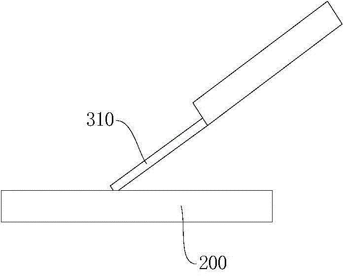
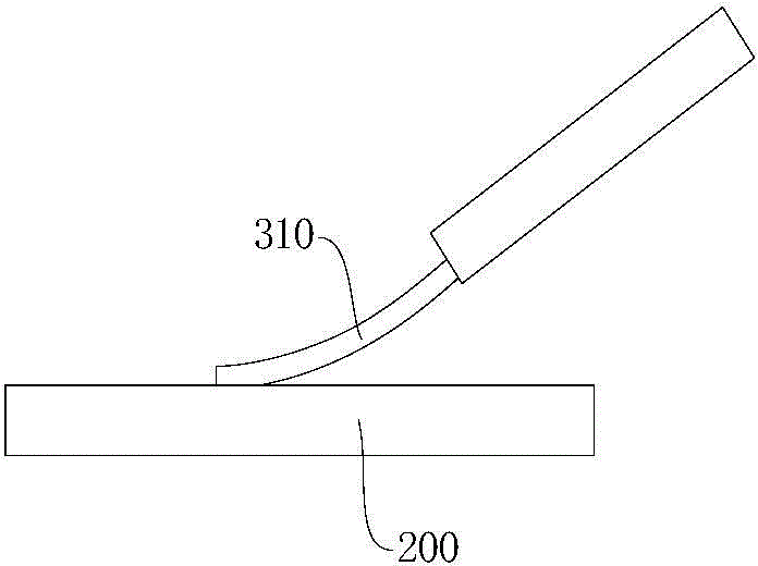
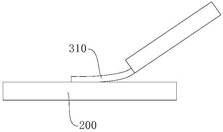
technical field [0001] The invention relates to the technical field of testing, in particular to a microprobe and a preparation method thereof. Background technique [0002] With the advancement of Micro-electromechanical Systems (MEMS) and nanotechnology, microprobes are increasingly used in scanning probe microscopes, tunnel sensors, micro-nano processing, and high-density data storage. [0003] refer to Figure 1a to Figure 1c , the microprobe provided by the prior art includes one or more cantilever beams 310 , and the end of each cantilever beam 310 can establish an electrical connection with the surface of the test sample 200 . When the test sample 200 is tested, at first the front end of the cantilever beam 310 of the microprobe needs to be contacted with the surface of the test sample 200, and then a certain pressure is applied to the cantilever beam 310 to make it deform, so that the cantilever beam 310 The tip has a larger area of ​​contact with the test sample 20...

Claims


Application Information

Patent Timeline
Patent Type & Authority Applications(China)
IPC IPC(8): G01R1/067B81B3/00B81B7/02B81C1/00
Inventor 沈文江贺世龙郭帅
Owner SUZHOU INST OF NANO TECH & NANO BIONICS CHINESE ACEDEMY OF SCI
Why Eureka
Try Eureka