
Graphics signal generation device and method based on fpga

A graphic signal and generating device technology, applied in nonlinear optics, instruments, optics, etc., can solve problems such as the inability to meet the detection requirements of high-resolution liquid crystal display modules

Active Publication Date: 2017-08-29
WUHAN JINGCE ELECTRONICS GRP CO LTD
View PDF6 Cites 0 Cited by
  • Summary
  • Abstract
  • Description
  • Claims
  • Application Information

AI Technical Summary

Problems solved by technology

[0003] In the prior art, there is no graphic signal generating device that can simultaneously generate logic screens and BMP images for liquid crystal module detection, which cannot meet the requirements of high-resolution liquid crystal display module detection

Method used


Image

  • Graphics signal generation device and method based on fpga

Examples


Embodiment Construction

[0039] Below in conjunction with accompanying drawing and specific embodiment the present invention is described in further detail:

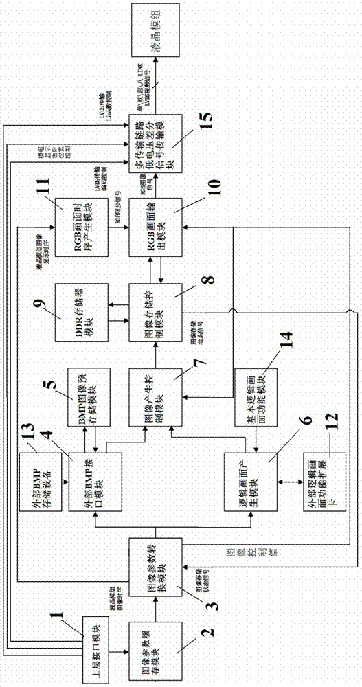
[0040] Such as figure 1 Described graphic signal generation device based on FPGA, it comprises upper layer interface module 1, image parameter cache module 2, image parameter conversion module 3, external BMP interface module 4, logic picture generation module 6, image generation control module 7, image storage Control module 8, RGB picture output module 10, RGB picture timing generation module 11 and multi-transmission link low-voltage differential signal transmission module 15;

[0041] Wherein, the logical picture parameter output end of the upper layer interface module 1 is connected to the signal input end of the image parameter buffer module 2, and the signal output end of the image parameter buffer module 2 is connected to the logical picture buffer parameter input end of the image parameter conversion module 3. The logical picture param...


PUM


Abstract

The invention relates to an FPGA-based figure signal producing device. The FPGA-based figure signal producing device comprises an upper layer interface module, an image parameter caching module, an image parameter conversion module, an external BMP interface module, a logic picture producing module, an image producing control module, an image storage control module, an RGB (red, green and blue) picture output module, an RGB picture timing sequence producing module and a multi-transmission-link low-voltage differential signal transmission module. The FPGA-based figure signal producing device can achieve a function of displaying logic pictures of BMP images and different patterns through an FPGA.

Description

technical field [0001] The invention relates to the technical field of display and testing of liquid crystal modules, in particular to an FPGA (Field-Programmable Gate Array, Field Programmable Gate Array)-based graphics signal generation device and method. Background technique [0002] As the resolution of liquid crystal display modules increases and the display effect becomes clearer and clearer, the technical requirements for the development, production, and testing of modules are also getting higher and higher. Therefore, in the detection of the module, it is necessary to detect the working status of each pixel of the module, and to detect the effect of the overall picture displayed by the module. In order to achieve these two goals, it is necessary to use different types of The former needs to display the logical picture (that is, the accurate and regular picture generated by the image signal source through its own calculation and processing), and the latter needs to di...

Claims


Application Information

Patent Timeline
Patent Type & Authority Patents(China)
IPC IPC(8): G02F1/13G09G3/00
CPCG02F1/1309G09G3/006
Inventor 彭骞朱亚凡欧昌东许恩邓标华沈亚非陈凯
Owner WUHAN JINGCE ELECTRONICS GRP CO LTD
Learn More