Camera intrinsic and extrinsic parameter automatic calibration method based on directional calibration target

A technology of automatic calibration and internal and external parameters, applied in image data processing, image analysis, instruments, etc., can solve inflexibility; around 1999, Microsoft Research Institute, unable to judge the rotation direction of a plane target without directional information, etc.

Active Publication Date: 2015-09-23
HEFEI UNIV OF TECH
View PDF5 Cites 38 Cited by
  • Summary
  • Abstract
  • Description
  • Claims
  • Application Information

AI Technical Summary

Problems solved by technology

[0003] In 1986, Roger Tsai proposed a camera calibration algorithm based on radial constraints, which required a 3D stereo target, making the calibration process inflexible; around 1999, Zhang Zhengyou (Z.Y Zhang) of Microsoft Research Institute proposed a camera calibration based on a plane target Algorithm, the calibration algorithm uses a plane target without direction information, the rotation direction of the plane target without direction information cannot be judged during the calibration process, and the camera calibration algorithm based on the plane target proposed by Zhang Zhengyou (Z.Y Zhang) requires the camera to capture the complete However, in practical applications, it is often necessary to judge the rotation direction of the planar target, and the camera often captures a local planar target during the actual calibration process. For example, when performing binocular camera calibration, the binocular camera system needs to simultaneously shoot the For the same plane target, it is necessary to determine the rotation direction of the plane target at this time, thereby establishing a target coordinate system with a fixed position relative to the plane target. The left and right cameras in the binocular camera system have a common target coordinate system. Using the target coordinate system as the transformation intermediary, the spatial position relationship between the left and right cameras can be calculated. When the public field of view of the left and right cameras is small, both the left and right cameras will capture the local planar target

Method used


Image

  • Camera intrinsic and extrinsic parameter automatic calibration method based on directional calibration target
  • Camera intrinsic and extrinsic parameter automatic calibration method based on directional calibration target
  • Camera intrinsic and extrinsic parameter automatic calibration method based on directional calibration target

Examples


Embodiment Construction

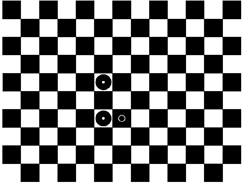
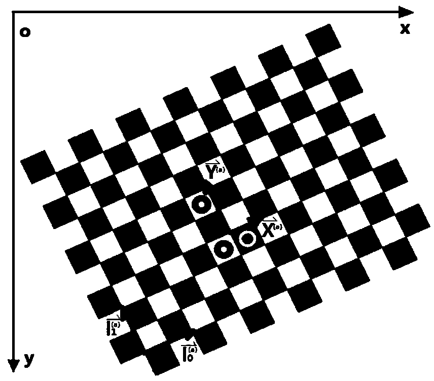
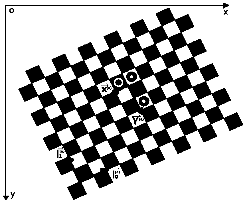
[0054] In this example, if figure 1 As shown, the directional calibration target is composed of a checkerboard consisting of black squares and white squares alternately and a directional sign pattern set near the center of the checkerboard; any two black squares connected diagonally or the intersection of any two diagonally connected white squares as the characteristic corners of the directional calibration target; the checkerboard contains M rows×N columns of characteristic corners; M and N are both positive integers; black squares and The side lengths of the white squares are all W; W>0; in this embodiment, if figure 1 The shown directional calibration target contains 9 rows × 12 columns of characteristic corner points; the side lengths of the black square and white square of the directional calibration target are both 18 mm;

[0055] The directional sign pattern is composed of 3 small sign pictures; the 3 small sign pictures are respectively the first sign picture, the sec...


PUM


Abstract

The invention discloses a camera intrinsic and extrinsic parameter automatic calibration method based on a directional calibration target. The method is characterized in that subpixel coordinates of all feature angular points in a target image are extracted by use of an improved Harris angular point detection algorithm; a target coordinate system is established by use of a directional symbol pattern on the calibration target, so as to determine and acquire target coordinates in the target coordinate system respectively corresponding to all feature angular points in the target image; rotation and translation of the calibration target in a three-dimensional space are estimated by use of a plane target space posture estimation algorithm, so as to realize rotation direction judgment of the directional calibration target; and G calibrated images meeting conditions are acquired, then camera intrinsic and extrinsic parameters are resolved by use of a Zhengyou Zhang calibration algorithm. Through adoption of the method, automatic calibration of camera intrinsic and extrinsic parameters can be realized, so that flexibility and practicability of calibration of camera intrinsic and extrinsic parameters are improved.

Description

technical field [0001] The invention relates to the field of camera calibration methods in computer vision, in particular to an automatic calibration method for camera internal and external parameters based on directional calibration targets. Background technique [0002] Computer vision technology is widely used in industrial control, metrology and other fields. Computer vision technology mainly uses camera imaging to obtain three-dimensional information of the measured object in space through image information, thereby reconstructing and identifying the object. The fundamental problem of computer vision technology is camera calibration. The mapping relationship between three-dimensional coordinates of space and two-dimensional coordinates of images can be obtained through camera calibration technology. Camera calibration technology is the research focus of computer vision measurement technology. The task of camera calibration is to solve the Internal and external parameter...

Claims


Application Information

Patent Timeline
Patent Type & Authority Applications(China)
IPC IPC(8): G06T7/00
CPCG06T7/80
Inventor 卢荣胜殷玉龙
Owner HEFEI UNIV OF TECH
Why Eureka
Try Eureka