Method for producing polymer motor vehicle component

A technology of motor vehicles and polymers, which is applied to vehicle parts, manufacturing tools, workpieces, etc., can solve the problems of structural limitations, unevenness, inflexible and expensive polymer motor vehicle parts, etc., to reduce costs and improve flexibility Effect

Active Publication Date: 2015-09-23
レーアウオートモーティヴソシエタスヨーロピアウントコンパニーコマンディートゲゼルシャフト
View PDF4 Cites 0 Cited by
  • Summary
  • Abstract
  • Description
  • Claims
  • Application Information

AI Technical Summary

Problems solved by technology

Another disadvantage is that the embossing radii produced by a correspondingly configured punch on the edge of the perforation can be uneven, especially in the case of curved surfaces
In addition, a restricted degree of structu...

Method used


Image

  • Method for producing polymer motor vehicle component
  • Method for producing polymer motor vehicle component
  • Method for producing polymer motor vehicle component

Examples


Embodiment Construction

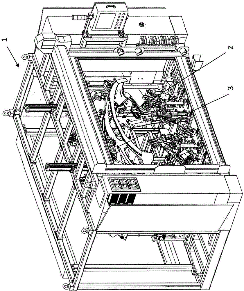
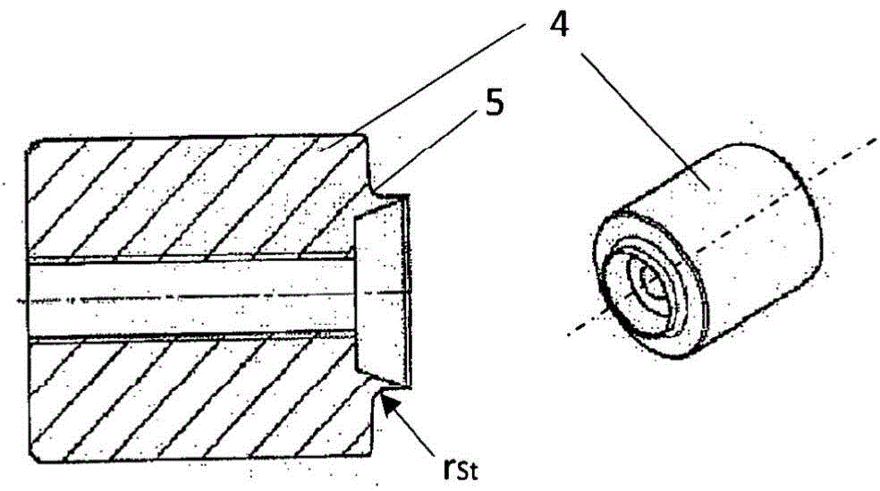
[0028] figure 1 A stamping device 1 known from the prior art is shown, which is generally used for forming perforations in polymeric motor vehicle components. exist figure 1 Such a motor vehicle component in the form of a bumper 2 can likewise be seen in FIG. According to the perforation to be formed on the stamping device 1 ( figure 1 Clearly visible in one of the perforations 3) is fitted with a different punch ( figure 2 One of the punches 4) is exemplarily shown in . figure 2 The sectional view of the punch 4 on the left in the center shows that the punch is provided for the radius embossing in the processing area 5 radius r St . In particular, it can be seen from the 3D view on the right of the punch 4 that it is cylindrical and can accordingly only be used to produce circular holes with a precisely defined diameter. The sharp edges of the corresponding perforations formed by the punching process are smoothed by the radius embossing.

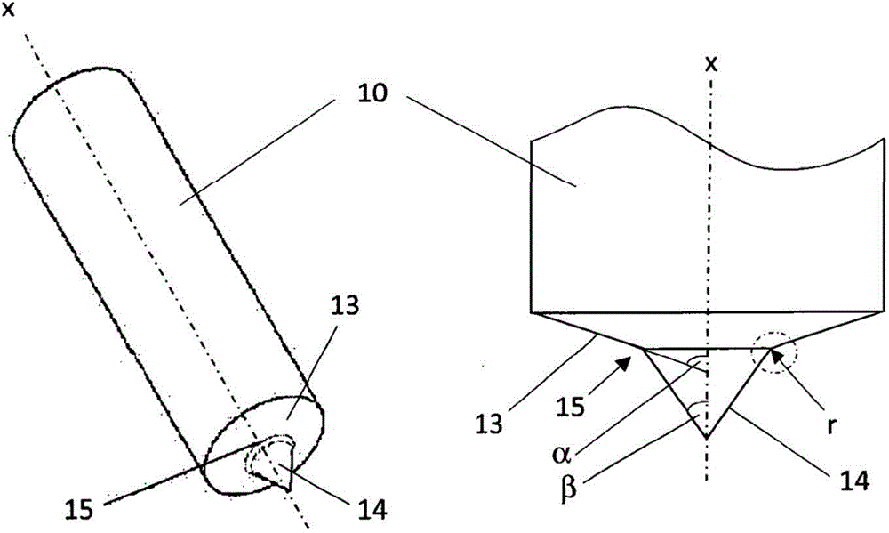
[0029] According to the me...


PUM


Abstract

The invention relates to a method for producing a polymer motor vehicle component (2), in particular an outer add‑on part in the form of a bumper, spoiler, sill, mud guard or the like. First of all, a polymer body shell part (6) is produced, preferably by means of an injection‑moulding method, wherein, then, at least one aperture (3) is produced in the body shell part (6), optionally by means of a first automated method step, the aperture then defining an inner border (7) of the body shell part (6), and wherein, then, in a separate, second automated method step, a stamped formation (R) of a radius onto the peripheral edge (9) formed by the outer body shell‑part surface (8) and inner border (7) and/or onto an outer edge formed by the outer border of the body shell part (6) takes place by a stamping tool (10) having a contour corresponding to the desired radius (r) of the stamped formation (R) being pressed along the inner border (7) against the peripheral edge (9) and/or along the outer border of the body shell part (6) against the outer edge.

Description

technical field [0001] The invention relates to a method for the production of polymeric motor vehicle components, in particular bumpers, spoilers, beams, fenders or similar external additional parts, for which the polymer raw material is first produced, preferably by means of an injection molding process part. Background technique [0002] In particular in the case of relatively large plastic injection molded parts for the automotive industry, perforations in the form of holes or other, for example elongated recesses, are formed only after the injection molding process in order to avoid flow lines. Such perforations are required, for example, in modern bumpers in order to provide mounting holes for additional components, parking positioning systems, recesses for trailer couplers, headlight washer devices, side identifiers, etc. [0003] In the prior art, the required perforations are usually formed by punching. where the sharp edges formed on the punching edge pass throug...

Claims


Application Information

Patent Timeline
IPC IPC(8): B29C67/00B26D7/27B29C59/02B29C63/00
CPCB29C67/0048B29C67/0029B29L2031/3044B23K2201/006B29C67/0044B23K26/38B23K26/4065B23K2101/006B23K2103/42B23K2103/50B29C69/001B23C3/00B23C2226/61B29K2023/16B29K2023/12B29K2105/0088B29L2031/3005
Inventor H·斯坦
Owner レーアウオートモーティヴソシエタスヨーロピアウントコンパニーコマンディートゲゼルシャフト
Why Eureka
Try Eureka