Method for fabrication of photo-control panel comprising photo-reflector parts which are positioned in parallel

A manufacturing method and technology of light reflection, applied in optics, optical components, household appliances, etc., can solve problems such as practical obstacles and difficulty in manufacturing curved surfaces of light, and achieve the effect of increased strength and high precision

Inactive Publication Date: 2015-09-23
ASUKANET
View PDF9 Cites 11 Cited by
  • Summary
  • Abstract
  • Description
  • Claims
  • Application Information

AI Technical Summary

Problems solved by technology

[0003] However, for the optical system described in Patent Document 1, it is extremely difficult to manufacture the light-bending surface composed of reflective surface-symmetric imaging elements, which hinders its practical application.

Method used


Image

  • Method for fabrication of photo-control panel comprising photo-reflector parts which are positioned in parallel
  • Method for fabrication of photo-control panel comprising photo-reflector parts which are positioned in parallel
  • Method for fabrication of photo-control panel comprising photo-reflector parts which are positioned in parallel

Examples


Embodiment Construction

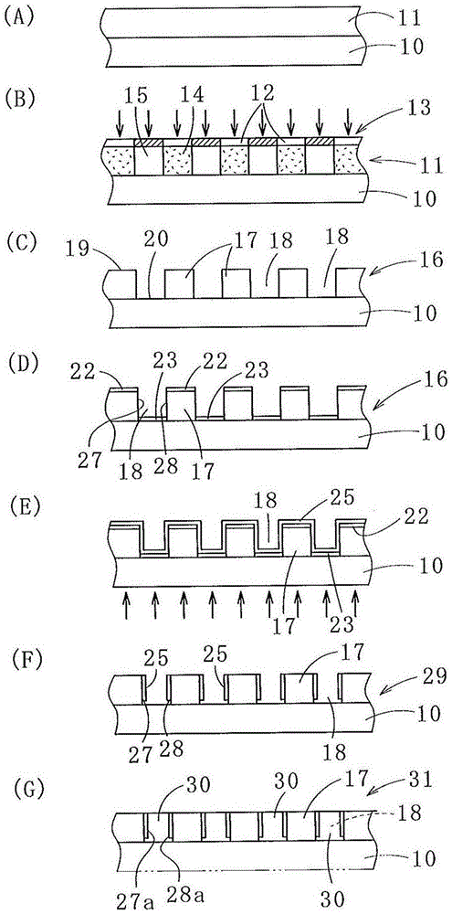
[0043] Next, a method of manufacturing a light control panel provided with light reflecting portions arranged in parallel according to a first embodiment of the present invention will be described with reference to the attached drawings.

[0044] like figure 1As shown in (A), an ultraviolet curable resin layer 11 is formed by applying an ultraviolet curable resin to one surface of a glass plate 10 as an example of a transparent plate-shaped optical material with a uniform thickness (for example, 10 to 500 μm). In addition, instead of the glass plate 10, a quartz plate or transparent plastic may be used. Moreover, when removing or peeling this glass plate 10 in a later process, a transparent peeling layer (for example, thermoplastic resin) is formed in advance on the surface of the glass plate 10.

[0045] Next, if figure 1 As shown in (B), the upper part of the ultraviolet curable resin layer 11 is covered with a mask 13 having parallel slits 12 , and ultraviolet rays are ...


PUM


Abstract

Provided is a method for fabrication of a photo-control panel, comprising: a first step of preparing a transparent uneven board (16) with quadrilateral cross-section depressions (18) which are formed by parallel banks (17) thereof; a second step of covering obverse faces (19) of the banks (17) and bottom faces (20) of the depressions (18) with ultraviolet projection peeling resins (22, 23); a third step of forming metal vapor deposition upon the obverse face of the uneven board (16) whereupon the obverse faces (19) of the banks (17) and the bottom faces of the depressions (18) are covered with the ultraviolet projection peeling resins (22, 23); and a fourth step of projecting ultraviolet from the rear face of the uneven board (16), and removing the ultraviolet projection peeling resins (22, 23), the obverse faces whereof have had the metal vapor deposition carried out thereupon. Photo-reflector parts are formed upon parallel opposing lateral faces (27, 28) of the depressions (18).

Description

technical field [0001] The present invention relates to an optical imaging device using first and second light control panels formed by arranging strip-shaped planar light reflecting portions (mirror surfaces) at regular intervals, and to inexpensively manufacturing the first and second light control panels Two light control panel method. Background technique [0002] An optical system has been proposed as an optical imaging device for forming a stereoscopic image using light (scattered light) emitted from the surface of an object, which has a ray-curving surface composed of a reflective surface-symmetric imaging element, the reflective surface The imaging element is said to be a unit optical element having two light-reflecting part elements that are orthogonal to each other and regularly formed on a plurality of (most) planes; The emitted light is reflected by the light reflection part through the light curved surface, and then transmitted through the light curved surface,...

Claims


Application Information

Patent Timeline
Patent Type & Authority Applications(China)
IPC IPC(8): G02B5/00G02B5/08G02B27/22G02B30/30
CPCG02F1/1333G02B27/2214G02B5/00G02B30/35G02B30/30B29D11/00596B29D11/0073G02B30/27G02B30/56
Inventor 大坪诚
Owner ASUKANET
Why Eureka
Try Eureka