Internal and external cooling structure for high-speed motorized spindle

A high-speed motorized spindle and cooling structure technology, applied in cooling/ventilation devices, electromechanical devices, electrical components, etc., can solve the problems of increased bearing wear and heat, high temperature, limited heat exchange power, etc., to reduce temperature rise, improve use Longevity, effect of improving machining accuracy and surface finish quality

Inactive Publication Date: 2015-09-30
ANYANG INST OF TECH
View PDF5 Cites 18 Cited by
  • Summary
  • Abstract
  • Description
  • Claims
  • Application Information

AI Technical Summary

Problems solved by technology

The traditional cooling method is to add a spiral cooling water channel between the motor stator and the shell, and add an annular water channel between the front bearing seat and the shell, and connect it through the water inlet and outlet joints on the rear cover, and the internal cooling The water takes away the heat from the stator and front bearing of the motor to cool the front bearing and stator. However, the rotor and rear bearing, which account for 1 / 3 of the heat generated by the motor, have not been effectively cooled, thus forming an external cooling system for the electric spindle. Phenomenon of internal heat
The thermal expansion of the spindle has a fatal effect on the machining accuracy. If the diameter of the spindle center is calculated as 0.5m, then according to the thermal expansion theory of the metal, if the temperature of the spindle center rises by 1°C, the length of the spindle will extend. The length is 0.005m. If the thermal deformation caused by this is not handled properly, it will seriously affect the machining accuracy and surface processing quality of the electric spindle on the one hand. On the other hand, because the temperature of the outer ring of the bearing is higher than that of the inner ring, the preload of the bearing Increased, further aggravated the wear and heat of the bearing, affecting the service life of the bearing
Aiming at this phenomenon, there is currently a shaft cooling method: a cooling heat pipe is installed on the shell of the electric spindle and the shaft. Although this cooling method can cool the electric spindle to a certain extent, this cooling The cooling medium of this method is not liquid but air. Since the heat exchange power of air is limited, this method cannot effectively solve the heat dissipation problem of the electric spindle under long-term work.

Method used


Image

  • Internal and external cooling structure for high-speed motorized spindle
  • Internal and external cooling structure for high-speed motorized spindle
  • Internal and external cooling structure for high-speed motorized spindle

Examples


Embodiment Construction

[0020] The specific implementation manners of the present invention will be described in further detail below in conjunction with the accompanying drawings.

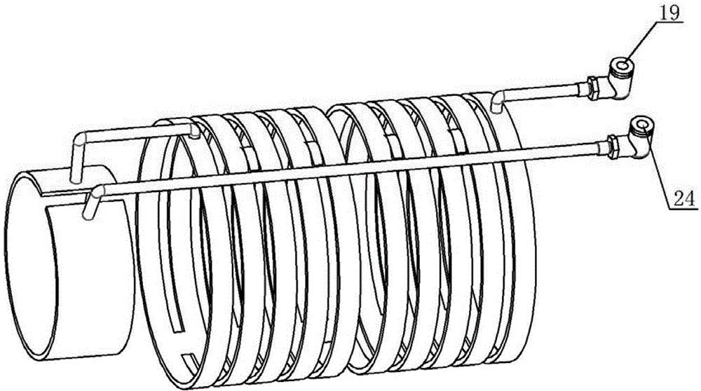
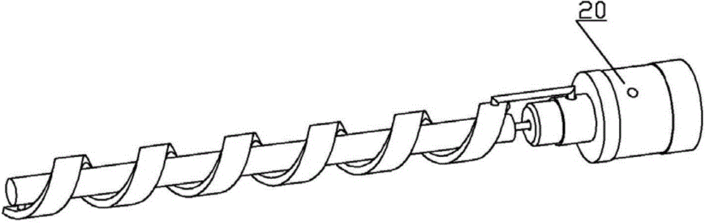
[0021] According to Figure 1 to Figure 4 It can be seen that the cooling structure of the present invention mainly involves: screw 1, transmission key 2, front cover 3, screw 4, housing 5, sealing cover 6, front bearing 7, front bearing seat 8, set screw 9, balance Ring 10, rotor 11, stator 12, set screw 13, rotor nut 14, O-ring 15, main shaft inner water jacket 16, rear bearing seat 17, gland 18, cooling water outlet joint 19, rotary joint 20, code Disk base nut 21, screw 22, code disk 23, cooling water inlet joint 24, code disk base 25, rear bearing nut 26, rear bearing 27, rear bearing retaining ring 28, rotor inner sleeve 29, stator inner water jacket 30, keys 31. Front bearing nut 32, sealing ring 33, O-shaped sealing ring 34, main shaft 35. Wherein the electric spindle front bearing 7 is installed in the front b...


PUM


Abstract

The invention provides an internal and external cooling structure for high-speed motorized spindle. According to the structure, cooling water channels are additionally arranged on a casing of the motorized spindle and a front bearing pedestal of the motorized spindle, and a spiral cooling water channel is arranged in the spindle, so that all the main heating components such as a motor stator, a motor rotor, a front bearing and a back bearing of the motorized spindle can be efficiently cooled, therefore, the temperature rising of the motorized spindle is effectively controlled, the service life of a motor and the service life of bearings can be prolonged, and the machining precision and surface machining quality of the motorized spindle are greatly improved by virtue of the reduction of thermal deformation.

Description

technical field [0001] The invention relates to an internal and external cooling structure of a high-speed electric spindle, in particular to a cooling structure for simultaneously cooling the electric spindle internally and externally. Background technique [0002] The main feature of the high-speed electric spindle is that the stator and rotor of the motor are directly installed inside the spindle to form a mechatronic electric spindle. Thus, the "zero transmission" of the spindle system is realized, which has the advantages of compact structure, small moment of inertia, fast start and stop speed, easy to realize stepless speed regulation and precise control, etc. is extremely unfavorable. The built-in electric spindle is mainly composed of a built-in servo motor, front and rear support bearings, a main shaft and a housing, among which the built-in servo motor and the front and rear bearings are the main heating components of the electric spindle. Temperature rise is an ...

Claims


Application Information

Patent Timeline
Patent Type & Authority Applications(China)
IPC IPC(8): B23Q11/12H02K9/19
CPCB23Q11/127H02K9/19
Inventor 李安玲何强李军段非吴耀春张国烨李丽丽李均张勇
Owner ANYANG INST OF TECH
Why Eureka
Try Eureka