Furnace nose for hot-dip galvanizing with detachable slag discharge pipe and method of use thereof
A slag discharge pipe and hot-dip galvanizing technology, applied in hot-dip galvanizing process, coating, metal material coating process, etc., can solve the problems of affecting the surface quality of strip steel, consuming man-hours and man-hours, and reducing production efficiency, etc., to achieve Superior slag removal effect, time and labor saving, high galvanizing quality effect
- Summary
- Abstract
- Description
- Claims
- Application Information
AI Technical Summary
Problems solved by technology
Method used
Image
Examples
Embodiment 1
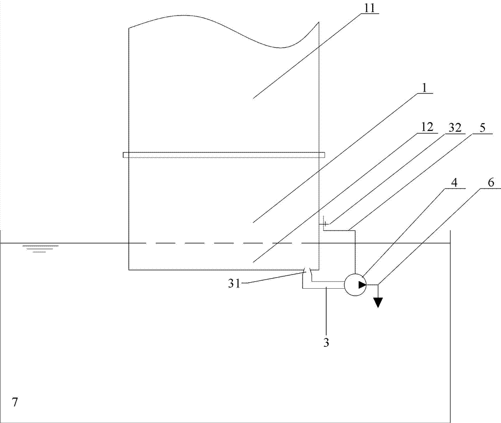
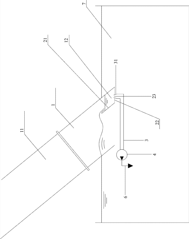
[0031] A furnace nose with a detachable slag discharge pipe for hot-dip galvanizing, including a furnace nose body 1, a partition plate 21, a bottom plate 22, a slag discharge pipe 3, a liquid zinc suction pump 4, a support 5 and a liquid zinc discharge pipe 6, such as figure 1 and figure 2 As shown, the specific structure is:
[0032] The furnace nose body 1 is arranged at the outlet end of the annealing furnace chute 11, the lower half of the inner cavity of the furnace nose body 1 is provided with a partition 21, and the two sides of the partition 21 are respectively fixed on the inner side wall of the furnace nose body 1, The partition plate 21 divides the lower half of the inner cavity of the furnace nose body 1 into two sections, one of the two sections is used as the slagging funnel 12, and the bottom of the slagging funnel 12 is closed with a bottom plate 22, and the bottom plate 22 is close to There are two slag discharge holes 23 at intervals on the outer edge, an...
Embodiment 2
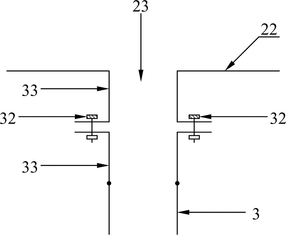
[0047] A furnace nose with a detachable slag discharge pipe for hot-dip galvanizing, including a furnace nose body 1, a partition plate 21, a bottom plate 22, a slag discharge pipe 3, a liquid zinc suction pump 4, a support 5 and a liquid zinc discharge pipe 6, such as image 3 As shown, the slag discharge pipe 3 is fixed on the slag discharge hole 23 in the following manner: one end of the slag discharge pipe 3 and the outer end of the slag discharge hole 23 are respectively fixed with a flange joint 33, and the flange joint 33 of the slag discharge pipe 3 and the The flange joints 33 of the slag discharge hole 23 are attached to each other with their respective flange chassis and fixed with fastening bolts 32; the suction port of the zinc liquid suction pump 4 and the outlet end of the slag discharge pipe 3 are connected by threads. Other structures are all the same as in Embodiment 1.
[0048] Using method is the same as embodiment 1.
PUM
 Abstract
Description
Claims
Application Information
 - R&D
- Intellectual Property
- Life Sciences
- Materials
- Tech Scout
- Unparalleled Data Quality
- Higher Quality Content
- 60% Fewer Hallucinations
Browse by: Latest US Patents, China's latest patents, Technical Efficacy Thesaurus, Application Domain, Technology Topic, Popular Technical Reports.
© 2025 PatSnap. All rights reserved.Legal|Privacy policy|Modern Slavery Act Transparency Statement|Sitemap|About US| Contact US: help@patsnap.com


