
Concrete delivery system and concrete delivery vehicle with the delivery system

A concrete conveying vehicle and conveying system technology, applied in the direction of road bottom layer, building, infrastructure engineering, etc., can solve the problems of hindering construction progress, waste of resources, waste of manpower and material resources, etc., and achieve the goal of increasing the effective construction scope and ensuring the quality of the project Effect

Active Publication Date: 2017-01-25
SHANDONG UNIV +1
View PDF5 Cites 0 Cited by
  • Summary
  • Abstract
  • Description
  • Claims
  • Application Information

AI Technical Summary

Problems solved by technology

[0003] In the concrete pouring of small structures where the construction level of the expressway is lower than the ground, it is necessary to use a concrete pump truck to transport the concrete. The concrete pump truck has certain advantages in pouring high-rise buildings, but in pouring small In the structure, it will cause a waste of manpower and material resources. In the construction of expressways in plain areas, there are a large number of small structures such as gravity retaining walls and culverts. It is inevitable to use concrete pump trucks for construction in such a large area. It will hinder the construction progress, and the above two will work together to cause a lot of waste of resources and economic losses

Method used


Image

  • Concrete delivery system and concrete delivery vehicle with the delivery system
  • Concrete delivery system and concrete delivery vehicle with the delivery system
  • Concrete delivery system and concrete delivery vehicle with the delivery system

Examples


Embodiment 1

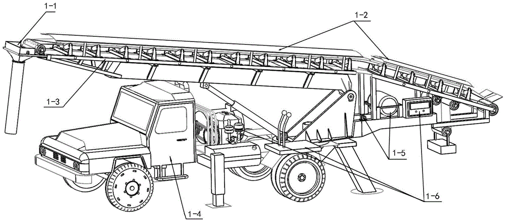
[0049] Embodiment 1: A kind of concrete transmission system 1-3, its structure reference image 3 , Figure 3a , Figure 4 and Figure 4a As shown, it includes: a rotating support 3-8, the rotating support 3-8 is fixedly connected with the tail support frame 3-9, the front end of the tail support frame 3-9 is hinged with the hydraulic lifting arm 3-7, and the tail support frame The upper end of 3-9 is hinged with the load-bearing beam 3-6, and the hydraulic lifting arm 3-7 can drive the load-bearing beam 3-6 to rotate with the hinge node of the load-bearing beam 3-6 and the tail support frame 3-9 as the center of circle;

[0050]The load-bearing beam 3-6 carries the conveyor belt 3-2 through the upper support frame 3-5, and the conveyor belt 3-2 is driven by the driving wheel and the driven wheel on the upper support frame 3-5 to realize its own movement; the driving wheel is mainly for the conveyor belt 3. The -2 transmission provides the power take-off. Driving wheel com...


PUM


Abstract

The invention relates to a concrete conveying system and a concrete transport vehicle with the same. The concrete conveying system mainly comprises a rotating support. The rotating support is fixedly connected with a tail portion supporting frame. The front end of the tail portion supporting frame is hinged to a hydraulic crane boom. The upper end of the tail portion supporting frame is hinged to a load-bearing beam. The hydraulic crane boom drives the load-bearing beam to rotate with the hinge joint of the load-bearing beam and the tail portion supporting frame as the circle center. The load-bearing beam carries a conveyor belt through an upper portion supporting beam. The conveyor belt is driven by a driving wheel and a driven wheel on the upper supporting frame to move. The end of the upper portion supporting frame is fixedly connected with a concrete guiding and pouring device which comprises a pouring guide pipe. The discharge port of the pouring guide pipe is lower than the conveyor belt so that concrete on the construction face lower than the horizontal face can be conveyed. By means of the transport vehicle, the construction progress of on-site concrete pouring can be accelerated, and the workability of concrete in the pouring period can be ensured.

Description

technical field [0001] The invention relates to the field of concrete engineering equipment, in particular to a concrete conveying system and a concrete conveying vehicle equipped with the conveying system. It is mainly used in the construction field of small structures whose construction level is lower than the ground, such as gravity retaining walls and culverts of expressways. Background technique [0002] With the rapid progress and development of the industry leading to a shortage of human resources, various enterprises strive to develop labor-saving machinery and promote the automation of various devices. Labor-saving machinery or automation relies heavily on conveyors for items. In industrial applications, conveyors can be seen everywhere. From conveying raw materials to conveying products to assembly line operations of products, all kinds of conveyors are used. The automation of modern industry is inseparable from conveyors. [0003] In the concrete pouring of smal...

Claims


Application Information

Patent Timeline
Patent Type & Authority Patents(China)
IPC IPC(8): E02D15/02E01F5/00
Inventor 崔伟张传德王术剑王大庆孟庆哲高峰姚元华房永晶秦海潮许展飞肖凯张爱然陈钰郑晓
Owner SHANDONG UNIV
Learn More