Grooving construction method for embedding underground continuous wall into rock

An underground diaphragm wall and trough-forming construction technology, which is applied in excavation, foundation structure engineering, construction, etc., can solve the problems of not meeting the construction control requirements, easy hole inclination at adjacent hole positions, and slow trough forming speed, etc., to meet the requirements of construction The effect of control requirements, fast groove forming speed, and small amount of waste pulp and residue

Active Publication Date: 2015-09-30
SHENZHEN SUNHUI MECHANICAL CO LTD
View PDF7 Cites 15 Cited by
  • Summary
  • Abstract
  • Description
  • Claims
  • Application Information

AI Technical Summary

Problems solved by technology

[0010] The purpose of the present invention is to provide a construction method for underground diaphragm wall into rock trough formation, aiming at solving the problem that the prior art underground diaphragm wall into rock trough formation method uses an impact hammer to impact the bedrock to form holes, and there are adjacent hole positions that are easy to be inclined and formed. Slow trough speed, troublesome construction, high cost and failure to meet construction control requirements

Method used


Image

  • Grooving construction method for embedding underground continuous wall into rock
  • Grooving construction method for embedding underground continuous wall into rock
  • Grooving construction method for embedding underground continuous wall into rock

Examples


Embodiment Construction

[0028] In order to make the objectives, technical solutions and advantages of the present invention clearer, the following further describes the present invention in detail with reference to the accompanying drawings and embodiments. It should be understood that the specific embodiments described here are only used to explain the present invention, but not to limit the present invention.

[0029] The implementation of the present invention will be described in detail below in conjunction with specific embodiments.

[0030] Reference Figure 4~10 Shown are the preferred embodiments provided by the present invention.

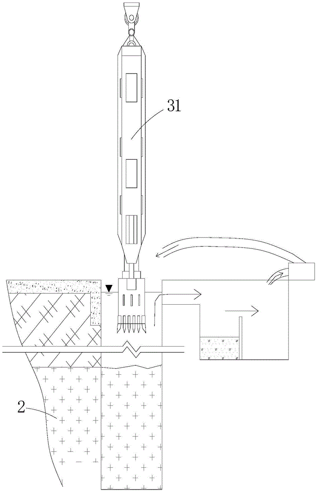
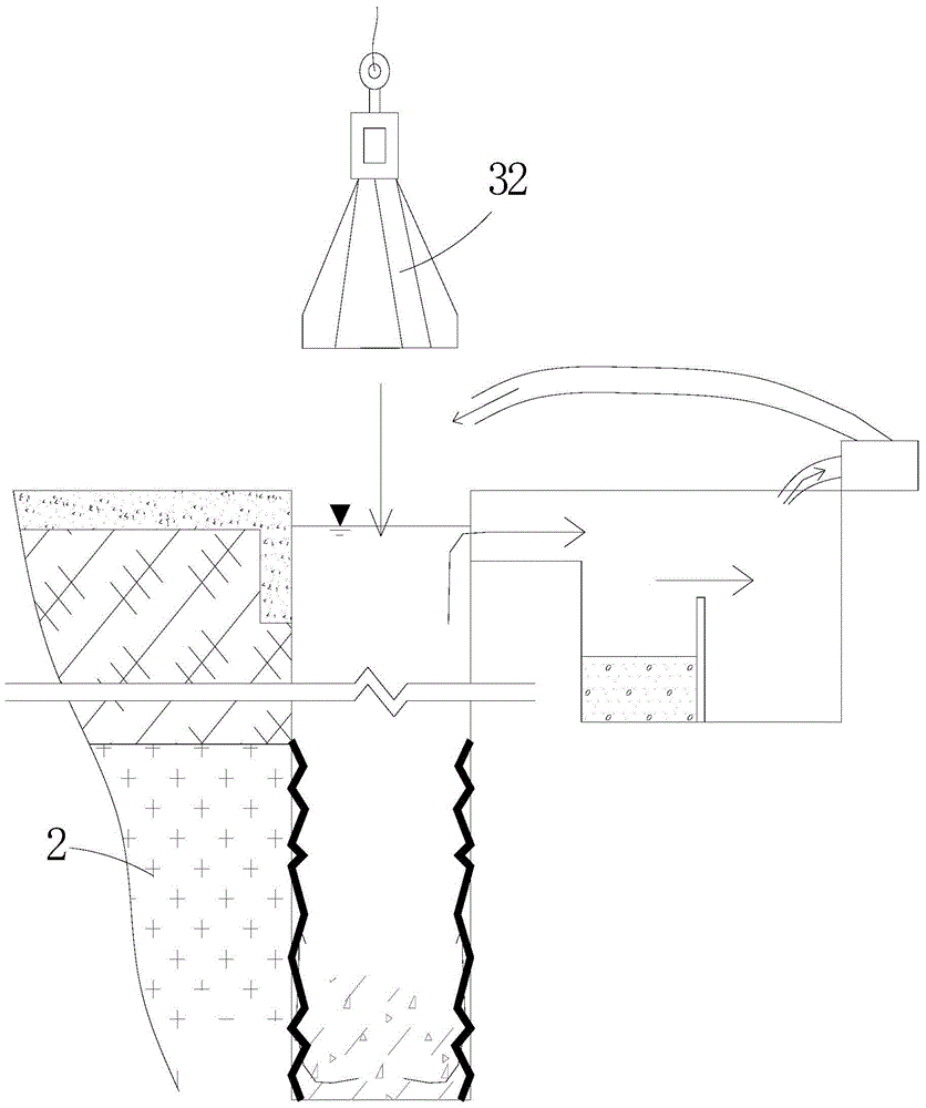
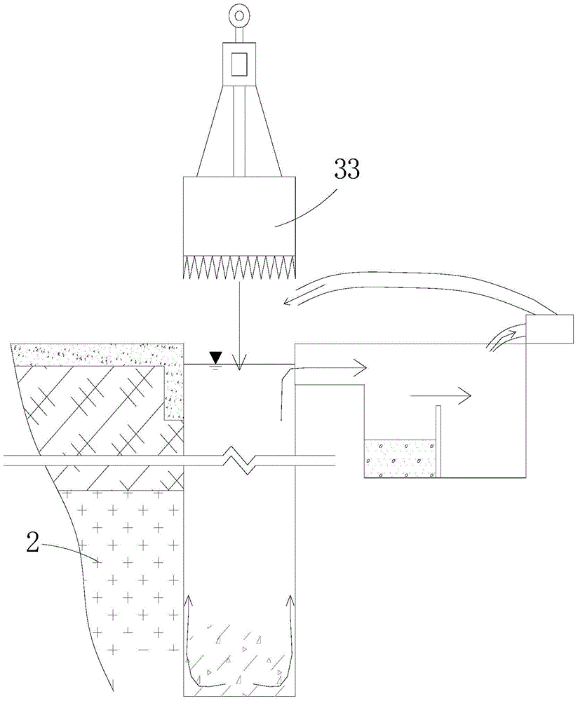
[0031] The construction method for rock-entering and trough formation of the underground continuous wall provided by this embodiment is used to form the trough section 13 which enters the rock so as to subsequently form the underground continuous wall which enters the rock. The bedrock 2 includes strongly weathered rock and the rock below the strong weathered rock. Wea...


PUM


Abstract

The invention relates to the technical field of embedding underground continuous walls into rock and grooving of the underground continuous walls and discloses a grooving construction method for embedding an underground continuous wall into rock. The method includes the steps that firstly, a grab bucket is used for excavating soil so that a groove can be formed, and a residual soil layer is reserved between the groove bottom and a rock face; secondly, a rotary excavating drilling tube is used for drilling holes in the residual soil layer and a seriously-weathered layer, a cutting-tooth drilling tube is used for drilling medium-weathered rock and micro-weathered rock, and rock entering holes in bed rock are formed; thirdly, the second step is repeated, and a plurality of rock entering holes are formed in the length extension direction of a groove segment; fourthly, a plane set-hammer is used for clearing away hard rock tooth edges. According to the construction method, the grooving speed is high, and on-site general layout and civilized construction are facilitated; meanwhile, the cutting-tooth drilling tube is used for performing rotary excavation and entering the rock to take a core, and impacting vibration is avoided; due to the fact that the grooving construction period is short, the exposing time of the groove wall is relatively short, the risk that groove wall soil collapses is reduced, the groove wall is stable, and construction cost is indirectly reduced; the residual soil layer is reserved on the rock face of the bed rock, the rotary excavating drilling tube plays a guiding role in the hole forming process, and the situation that because the inner rock face of the groove segment is inclined, hole drilling deflects is prevented.

Description

Technical field [0001] The invention relates to the technical field of underground continuous walls into rock formation troughs, in particular to a construction method of underground continuous walls into rock formation troughs. Background technique [0002] Currently, major cities have subways. For example, Shenzhen Special Economic Zone has subway lines 1, 2, 3, 4, and 5 in operation, and subway lines 7, 9, and 11 are under construction. Along the road, it plays a huge role in urban transportation and its economic construction. It is especially important to ensure the safety of the subway station and its tunnel section, and to ensure the normal operation of the subway. Therefore, the construction of buildings (structures) around the subway, especially the excavation of deep and large foundation pits within the affected area of ​​the subway, the subway management department has formulated special management regulations and control standards, such as: shock and vibration construc...

Claims


Application Information

Patent Timeline
Patent Type & Authority Applications(China)
IPC IPC(8): E02D17/06
Inventor 雷斌李榛叶坤柴源杨静张小花王雄凌利婷
Owner SHENZHEN SUNHUI MECHANICAL CO LTD
Why Eureka
Try Eureka