Node for connecting concrete-filled steel tube column and external wrapping U-shaped steel concrete composite beam

A technology for steel pipe concrete columns and connection nodes, which is applied in building components, earthquake resistance, construction, etc., and can solve problems such as limited scope of application, large number of openings, and increased construction difficulty

Inactive Publication Date: 2015-09-30
SHANDONG JIANZHU UNIV
View PDF4 Cites 6 Cited by
  • Summary
  • Abstract
  • Description
  • Claims
  • Application Information

AI Technical Summary

Problems solved by technology

[0014] (1) Since the bottom plate of the composite beam and the lower reinforced ring plate are lap welded, under the action of earthquake load, the weld seam is easy to crack and cannot meet the seismic requirements;
[0015] (2) Since the steel bars with negative bending moment all pass through the node area, there are many holes in the steel pipe wall, so the bearing capacity of the steel pipe is greatly weakened, and corresponding reinforcement measures need to be taken, such as repair welding steel plates, stiffeners, steel bars, etc. It not only increases the amount of steel used, but also increases the difficulty of construction;
[0016] (3) Since the side plate of the composite beam and the steel pipe wall are connected by welds, the on-site welding workload is large, which is not only laborious and time-consuming, but also the quality of the welds is difficult to guarantee, which is not conducive to the use of large-scale pr

Method used


Image

  • Node for connecting concrete-filled steel tube column and external wrapping U-shaped steel concrete composite beam
  • Node for connecting concrete-filled steel tube column and external wrapping U-shaped steel concrete composite beam
  • Node for connecting concrete-filled steel tube column and external wrapping U-shaped steel concrete composite beam

Examples


Example Embodiment

[0050] In order to clearly illustrate the technical features of this solution, the following describes the solution through specific implementations and in conjunction with the accompanying drawings.

[0051] Cutting limbs: refers to cutting off a part of the bottom plate of U-shaped steel as required.

[0052] Composite beam: refers to the abbreviation of the U-shaped steel concrete composite beam.

[0053] High-strength bolt: refers to a high-strength bolt, which is a standard part. Under normal circumstances, high-strength bolts can bear more load than ordinary bolts of the same specification.
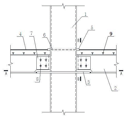
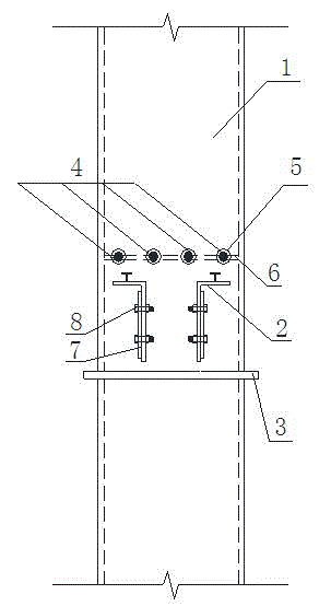
[0054] A connection node between a concrete-filled steel tube column and an outer U-shaped steel-concrete composite beam. As shown in the figure, it includes an outer ring plate 3 and a horizontal stiffening plate 6. The horizontal stiffening plate 6 is provided with pouring holes 12 and vent holes 11, The outer ring plate 3 is welded to the outer side of the steel pipe 1 at the bottom pla...


PUM


Abstract

The invention provides a node for connecting a concrete-filled steel tube column and an external wrapping U-shaped steel concrete composite beam. The node facilitates the pouring of concrete in a steel tube, easily guarantees pouring quality of concrete in a node area, is favorable for welding operation and easily guarantees weld seam quality. An outer annular plate is welded to the outer side of the steel tube at the position of a U-shaped steel base plate, the two opposite ends inside the outer annular plate in the length direction of the composite beam are connected with the U-shaped steel base plate having undergone limb cutting through butt joint weld seams, the weld seams do not crack easily, the connecting strength is high, and the vibration resistance is good. Sleeves capable of being movably connected with the ends of a hogging moment steel rib are arranged at the two opposite ends inside the steel tube in the length direction of the composite beam respectively; and the sleeves are welded to an outer wall of the steel tube. The structural type can reduce the weakening of steel tube bearing capacity caused by hole opening in a side wall of the steel pipe, the welding workload is reduced, and the construction and assembly are facilitated. To effectively transmit a load, horizontal reinforcing plates are fixedly welded to the positions of a steel tube inner cavity corresponding to the sleeves.

Description

technical field [0001] The invention relates to a concrete-filled steel pipe column and an outsourcing U-shaped steel-concrete composite beam, in particular to a connection node between a steel-pipe concrete column and an outsourcing U-shaped steel-concrete composite beam. Background technique [0002] Concrete-filled steel pipe column refers to the vertical member formed by filling concrete in the steel pipe. It has the advantages of high bearing capacity, good plasticity and ductility, high rigidity, convenient construction, and good fire resistance. It has received extensive attention from the engineering community in recent years. It is used more and more in multi-high-rise buildings and bridge engineering. According to different cross-sectional forms, CFST columns can be divided into circular CFST columns, rectangular CFST columns and polygonal CFST columns. Outer U-shaped steel-concrete composite beam is directly welded or cold-bent the steel plate into U-shaped steel...

Claims


Application Information

Patent Timeline
IPC IPC(8): E04B1/58E04B1/98
Inventor 周学军林彦杨融谦
Owner SHANDONG JIANZHU UNIV
Why Eureka
Try Eureka