[0039] Example one
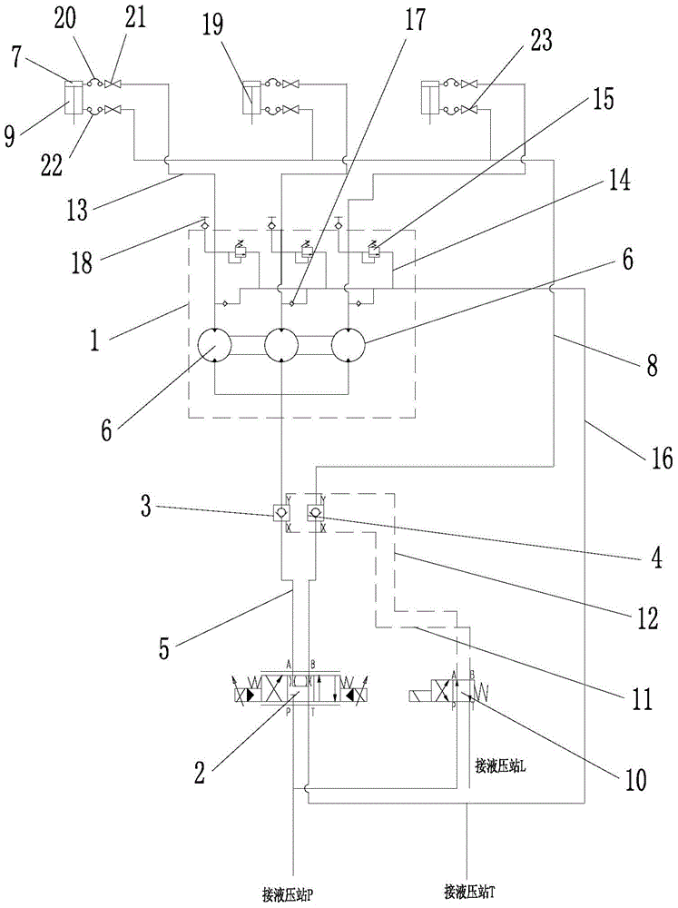
[0040] Such as figure 2 As shown, the hydraulic control system for the positioning accuracy of the inclination angle of the distribution chute of the present invention includes a hydraulic synchronous motor 1, a proportional valve 2, a first hydraulic control check valve 3, and a second hydraulic control check valve 4. The proportional valve 2 in this embodiment adopts a three-position four-way electro-hydraulic proportional valve. Other types of proportional valves can of course also be used, as long as they can achieve the same function, such as a servo proportional valve. The proportional valve 2 has the functions of stepless speed regulation and precise control of the oil supply, and can accurately position the distribution chute. The port P of the proportional valve 2 is connected to a high-pressure hydraulic oil source. figure 2 The oil port P of the proportional valve 2 is connected to the hydraulic station P, that is, the low-pressure oil in the oil tank of the hydraulic station is converted into high-pressure oil by the high-pressure oil pump. The oil port T of the proportional valve 2 is connected to the oil return pipe of the hydraulic station. In this embodiment, the oil port T of the proportional valve 2 is connected to the hydraulic station T. The oil port A of the proportional valve 2 is connected to one end of the first pipeline 5, and the other end of the first pipeline 5 is divided into three paths, and the three paths are respectively connected to the three shunts 6 of the hydraulic synchronous motor 1. Each splitter 6 of the hydraulic synchronous motor 1 is connected to a split oil pipe 13 respectively, and the splitter 6 is connected to the rodless cavity 7 of one of the cylinders through the split oil pipe 13 connected by itself, that is, three splitters 6 The rodless cavities 7 of the three oil cylinders are connected in one-to-one correspondence. The oil port B of the proportional valve 2 is connected to one end of the second pipeline 8, and the other end of the second pipeline 8 is divided into three paths, and the three paths are respectively connected to the rod cavities 9 of the three cylinders.
[0041] Continue to combine figure 2 , The first hydraulic control check valve 3 is connected in series on the first pipeline 5, and the first hydraulic control check valve 3 is connected with a control oil circuit. When the second pipeline 8 supplies oil to the rod chambers 9 of the three cylinders, the control oil circuit supplies oil to the control oil port X of the first hydraulic control check valve 3, so that the first hydraulic control check valve 3 is reversed. Guide through. When there is no control oil, the first hydraulic control check valve 3 allows the hydraulic oil to pass through the proportional valve 2 to the diverter 6 in one direction. The second hydraulic control check valve 4 is serially connected to the second pipeline 8, and the second hydraulic control check valve 4 is also connected with a control oil circuit. When the hydraulic synchronous motor 1 supplies oil to the rodless chambers 7 of the three cylinders, the control oil circuit supplies oil to the control oil port X of the second hydraulic control check valve 4, so that the second hydraulic control check valve 4 is reversed. When there is no control oil, the second hydraulic control check valve 4 makes the hydraulic oil flow from the proportional valve 2 to the rod cavity 9 in one direction.
[0042] In this embodiment, the first hydraulic control check valve 3 and the second hydraulic control check valve 4 share a control oil circuit, and a reversing valve 10 is provided on the control oil path. The reversing valve 10 in this embodiment is a two-position The four-way solenoid valve, of course, can also use other types of reversing valves. The control oil circuit includes an oil inlet control oil circuit 11 and an oil return control oil circuit 12. Specifically, such as figure 2 As shown, the oil port P of the reversing valve 10 is connected to a high-pressure hydraulic oil source (the high-pressure hydraulic oil source and the high-pressure hydraulic oil source of the proportional valve 2 share one, that is, the hydraulic station P). The oil port T of the reversing valve 10 is connected to the hydraulic station drain pipe, which is connected to the hydraulic station T in this embodiment. The oil port A of the reversing valve 10 is simultaneously connected to the drain port Y of the first hydraulic control check valve 3 and the second hydraulic control check valve 4 through the oil return control oil circuit 12, and the oil port B of the reversing valve 10 passes through The oil inlet control oil passage 11 is simultaneously connected with the control oil ports X of the first hydraulic control check valve 3 and the second hydraulic control check valve 4.
[0043] When the three oil cylinders are moving, if one of the oil cylinders moves in place or gets stuck, the hydraulic synchronous motor 1 will inevitably produce "holding pressure" or "emptying". In order to prevent this phenomenon, as a preferred solution of this embodiment, continue to combine figure 2 , Each branch oil pipe 13 is connected in parallel with an overflow pipe 14 respectively, and each overflow pipe 14 is respectively provided with a pressure limiting safety valve 15. The overflow pipeline 14 between the charge check valve 17 and the pressure limiting safety valve 15 is connected with an oil return pipeline 16 for returning the hydraulic oil in the overflow pipeline 14 to a hydraulic station or an oil tank. The pressure-limiting safety valve 15 will perform overload protection according to the set pressure value (the pressure of the pressure-limiting safety valve 15 is set to be about 15 bar higher than the normal cylinder working pressure), and the pressure-limiting safety valve 15 can simultaneously make the remaining cylinders run in place. Continue to combine figure 2 , The overflow pipeline 14 is also provided with a supplementary check valve 17, the cut-off end of the supplementary check valve 17 is connected with the bypass oil pipe 13, and the conducting end of the supplementary check valve 17 is connected with the pressure limiting safety valve 15. . When the "empty" of the hydraulic synchronous motor 1 occurs, the charge check valve 17 will be opened to prevent the cavitation damage caused by the vacuum.
[0044] As a further improvement, a pressure measuring joint 18 for detecting oil pressure is provided on the branch oil pipe 13. Combine figure 2 As shown, the pressure measuring connector 18 can be arranged at the connection between the branch oil pipe 13 and the overflow pipe 14 as in the connection method adopted in this embodiment.
[0045] Continue to combine figure 2 The second pipeline 8 is connected to the rod cavity 9 of the oil cylinder through a second hydraulic hose 22, and a second high-pressure ball valve 23 is provided near the second hydraulic hose 22; The rodless cavity 7 of the oil cylinder is connected by a first hydraulic hose 20, and a first high-pressure ball valve 21 is provided at the branch oil pipe 13 close to the first hydraulic hose 20. The arrangement of the first high-pressure ball valve 21 and the second high-pressure ball valve 23 can cut off the oil circuit when inspecting the oil cylinder. In addition, the oil cylinder in this embodiment is provided with a displacement sensor (not shown in the figure), which functions to detect whether the three oil cylinders are synchronized and to protect the hydraulic control system when the pressure limiting safety valve 15 fails.
[0046] When the hydraulic control system for the positioning accuracy of the inclination angle of the distribution chute of the present invention is installed, the hydraulic synchronous motor 1 can be installed on the top cover of the distributor to reduce the influence of the oil compression in the pipeline on the displacement fluctuation of the cylinder.
[0047] Combine below figure 2 Briefly describe the working process of the hydraulic control system for the positioning accuracy of the inclination angle of the distribution chute according to the present invention:
[0048] The cloth chute tilts downward (the piston rod 19 of the cylinder retracts): the proportional solenoid on the left side of the proportional valve 2 (three-position four-way electro-hydraulic proportional valve) is energized, and the solenoid generates thrust to push the spool to move to the right. PB is on and AT is on. When the electromagnet of the proportional valve 2 is energized, the electromagnet of the reversing valve 10 is energized, pushing the spool to move to the right, the PB of the reversing valve 10 is turned on, AT is turned on, and the port P of the reversing valve 10 The pressure oil enters the control oil port X of the first hydraulic control check valve 3 through the oil port B along the oil inlet control oil path 11. The control oil then passes through the oil drain port Y of the first hydraulic control check valve 3 and passes through the reversing valve The port AT of 10 is drained back to the hydraulic station L, and the first hydraulic control check valve 3 is reversely conducted. The high-pressure hydraulic oil of the hydraulic station P enters the rod cavity 9 of the three cylinders at the same time through the oil port PB of the proportional valve 2 along the second pipeline 8 through the second hydraulic control check valve 4, and supplies oil to the rod cavity 9 at the same time. The piston rod 19 is retracted. The hydraulic oil in the rodless cavity 7 of the oil cylinder enters the first pipeline 5 through the splitter 6 of the hydraulic synchronous motor 1 along the respective branch tubing 13 respectively, and then passes through the first hydraulic control check valve 3, and then through the proportional valve The 2 port AT returns to the hydraulic station T.
[0049] The cloth chute tilts upward (the piston rod 19 of the oil cylinder extends): the proportional solenoid on the right side of proportional valve 2 (three-position four-way electro-hydraulic proportional valve) is energized, and the solenoid generates thrust to push the spool to move to the left, the PA of proportional valve 2 Turn on, BT turns on. When the electromagnet of the proportional valve 2 is energized, the electromagnet of the reversing valve 10 is energized, pushing the spool to move to the right, the PB of the reversing valve 10 is turned on, AT is turned on, and the port P of the reversing valve 10 The pressure oil enters the control oil port X of the second hydraulic control check valve 4 through the oil port B along the oil inlet control oil path 11. The control oil then passes through the oil drain port Y of the second hydraulic control check valve 4 and passes through the reversing valve The port AT of 10 is drained back to the hydraulic station L, and the second hydraulic control check valve 4 is reversely conducted. The high-pressure hydraulic oil of the hydraulic station P enters the three coaxial shunts 6 of the hydraulic synchronous motor 1 through the port PA of the proportional valve 2 along the first pipeline 5 through the first hydraulic control check valve 3, and then divides them along the three lines respectively. The oil pipe 13 enters the three rodless chambers 7 of the oil cylinder to supply oil to the rodless chamber 7 at the same time, and the piston rod 19 extends. The hydraulic oil in the rod cavity 9 of the oil cylinder enters the second pipeline 8, and then returns to the hydraulic station T through the oil port B-T of the proportional valve 2 after passing through the second hydraulic control check valve 4.
[0050] It can be seen from the above description that the present invention uses the role of the three coaxial splitters 6 of the hydraulic synchronous motor 1 to distribute the same amount of oil to each cylinder by setting the hydraulic synchronous motor 1, and the coaxial splitter 6 can also perform Isolate the role of the three cylinders. Therefore, the synchronization of the three oil cylinders is ensured, so that the supporting ring driven by the three oil cylinders will not tilt, avoiding the wear between the guide wheel and the guide rail, and improving the service life of the distributor.