Separator with low noise device

A low-noise, separator technology, applied in the field of separators to reduce noise

Inactive Publication Date: 2015-09-30
苏细调
7 Cites 1 Cited by

AI-Extracted Technical Summary

Problems solved by technology

[0003] The invention provides a separator with a low-noise device, which solves the technical problem that the pig manure solid-liquid...

Abstract

The invention relates to a separator with a low noise device. The separator with the low noise device comprises a rack, a drying machine, a first screw conveyer, a cyclone dehumidifier and a hot air furnace, wherein the drying machine, the first screw conveyer, the cyclone dehumidifier and the hot air furnace are arranged on the rack. The drying machine is connected with the rack through rolling wheels, a driving motor is arranged at the lower end of the drying machine, the driving motor is connected with the drying machine through a belt bar, one end of the drying machine is communicated with the cyclone dehumidifier, the lower end of the cyclone dehumidifier is connected with the first screw conveyer, the first screw conveyer is fixed to the rack through supporting rods, the hot air furnace is fixed to the lower end of the left side of the drying machine through screw rods, a second screw conveyer is connected to the upper end of the left side of the drying machine, and the second screw conveyer is connected with a hopper through a feeding pipe. The separator with the low noise device has the advantages that a set of sound insulation plates are mounted on the two sides of the drying machine. The separator with the low noise device is effectively prevented from generating noise during work.

Application Domain

Drying solid materialsSound producing devices

Technology Topic

Screw conveyorDrive motor +3

Image

  • Separator with low noise device

Examples

  • Experimental program(1)

Example Embodiment

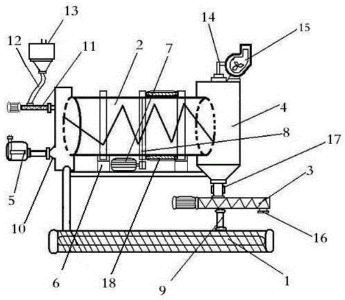
[0013] Example: such as figure 1 As shown, the separator of a low-noise device in this example includes a frame (1), a dryer (2), a first screw conveyor (3), and a dryer (2) arranged on the frame (1). Cyclone dehumidifier (4), hot air stove (5), the dryer (2) and the frame (1) are connected by a roller (6), and the lower end of the dryer (2) is provided with a drive motor (7), the drive motor (7) is connected to the dryer (2) through a belt strip (8), one end of the dryer (2) is connected with the cyclone dehumidifier (4), the cyclone A first screw conveyor (3) is connected to the lower end of the dehumidifier (4), and the first screw conveyor (3) is fixed to the frame (1) through a support rod (9), and the hot air stove (5) ) The screw (10) is fixed to the lower left end of the dryer (2), and the upper left end of the dryer (2) is connected to the second screw conveyor (11), and the second screw conveyor (11) passes The feeding pipe (12) is connected to the hopper (13). When in use, the wet pig manure is added to the hopper (13), and the second screw conveyor (11) is reached through the feeding pipe (12), so that the second screw conveyor ( 11) The wet pig manure is sent to the dryer (2), and the drive motor (7) runs the dryer (2) through the belt strip (8). At the same time, the hot blast stove (5) sucks in air and heats the air. The pig manure is dried and disinfected, which transports the internally processed solids to the cyclone dehumidifier (4), enters the first screw conveyor (3) and is discharged through the discharge port (16) at the lower end, and the cyclone dehumidifier (4) The hot and humid air inside is exhausted from the machine by the suction fan (15) to complete the drying and disinfection of pig manure.
[0014] It can be seen from Figure 1 that the upper end of the cyclone dehumidifier (4) is connected to the suction fan (15) through the through pipe (14), and the cyclone dehumidifier (4) is connected to the first screw conveyor (3). Connected by flange (17).

PUM

no PUM

Description & Claims & Application Information

We can also present the details of the Description, Claims and Application information to help users get a comprehensive understanding of the technical details of the patent, such as background art, summary of invention, brief description of drawings, description of embodiments, and other original content. On the other hand, users can also determine the specific scope of protection of the technology through the list of claims; as well as understand the changes in the life cycle of the technology with the presentation of the patent timeline. Login to view more.

Similar technology patents

Traffic sign detection method based on classification template matching

Owner:NO 8357 RES INST OF THE THIRD ACADEMY OF CHINA AEROSPACE SCI & IND

Classification and recommendation of technical efficacy words

  • reduce noise

Liver subsection method based on CT image and system thereof

InactiveCN101425186Areduce noiseavoid blur
Owner:HUAZHONG UNIV OF SCI & TECH

Noise reduction device

ActiveUS20100014683A1reduce noisehigh quality
Owner:PANASONIC CORP

Automatic image capture

ActiveUS20110170740A1reduce noiseenhance edge
Owner:NORTHWEST IP LLC +1

Shift register electrode, grid electrode driver, array substrate and display device

InactiveCN102654986AReduced Threshold Voltage Driftreduce noise
Owner:BOE TECH GRP CO LTD +1
Why Eureka
Try Eureka