Method and system for measuring frequency characteristics of high-speed FOG (Fiber Optical Gyroscope)

A fiber optic gyroscope and frequency characteristic technology, applied in frequency measurement devices, spectrum analysis/Fourier analysis, etc., can solve the problems of low frequency resolution of test results, limited number of test frequency points, and no phase characteristic measurement, etc., and achieve test speed. Fast, good suppression effect, low cost effect

Inactive Publication Date: 2015-09-30
ZHEJIANG UNIV
View PDF7 Cites 21 Cited by
  • Summary
  • Abstract
  • Description
  • Claims
  • Application Information

AI Technical Summary

Problems solved by technology

This method requires sweeping frequency testing. If a relatively complete frequency response function needs to be obtained, multiple sets of test frequency signals are required to measure at each test frequency, resulting in a long measurement time; at the same time, due to the limited number of test frequency points, the frequency of test results Low resolution, especially for high-speed fiber optic gyroscopes, it is very important to measure high-resolution frequency characteristics to evaluate its performance; there is no measurement for phase characteristics, or the phase estimation error is large

Method used


Image

  • Method and system for measuring frequency characteristics of high-speed FOG (Fiber Optical Gyroscope)
  • Method and system for measuring frequency characteristics of high-speed FOG (Fiber Optical Gyroscope)
  • Method and system for measuring frequency characteristics of high-speed FOG (Fiber Optical Gyroscope)

Examples


Embodiment Construction

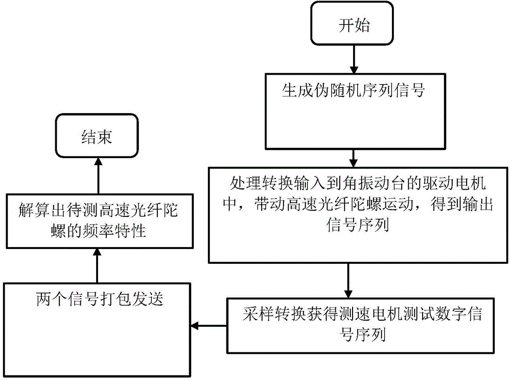
[0041] The present invention will be described in further detail below in conjunction with the accompanying drawings and specific embodiments.

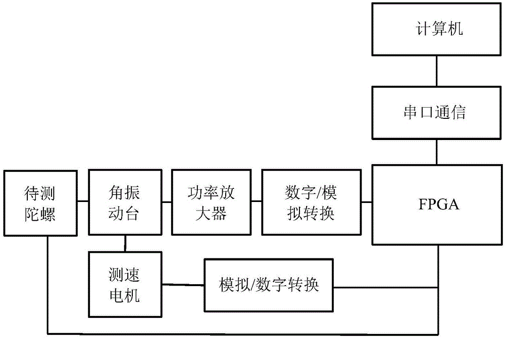
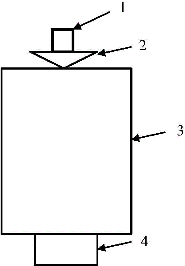
[0042] Implementing device of the present invention such as figure 2 As shown, the implementation device includes the drive motor 3 and the speed measuring motor 4 of the angular vibration table, the stage 2, the high-speed fiber optic gyro 1 to be tested and the FPGA processor, and the stage 2 is fixed on the rotating shaft of the drive motor 3. The high-speed fiber optic gyroscope 1 is placed on the stage 2, and the driving motor 3 and the speed measuring motor 4 are connected and rotated synchronously; the FPGA processor is connected to the driving motor 3 of the angular vibration table through a digital-to-analog converter and a power amplifier in turn, and the speed measuring motor 4 is passed through the analog and digital The converter is connected to the FPGA processor, the high-speed fiber optic gyroscope 1 to be tested is c...


PUM


Abstract

The invention discloses a method and a system for measuring frequency characteristics of a high-speed FOG (Fiber Optical Gyroscope). The method comprises the steps of logically generating a pseudorandom sequence test digital signal according to the generation of a pseudorandom sequence; processing and converting the pseudorandom sequence test digital signal into a pseudorandom sequence test analog signal, and inputting the pseudorandom sequence test analog signal to a driving motor of an angular vibration table to be used as a rotary input signal; enabling the angular vibration table to drive a to-be-measured high-speed FOG to run, and obtaining an output signal sequence of the to-be-measured high-speed FOG; collecting an angular speed analog signal of a speed measuring motor, and obtaining a digital signal sequence of the speed measuring motor; computing the output signal sequence of the to-be-measured high-speed FOG and the digital signal sequence of the speed measuring motor, and obtaining a frequency response function of the to-be-measured high-speed FOG, wherein the frequency response function comprises amplitude-frequency characteristics and phase-frequency characteristics; completing the measurement. The method disclosed by the invention can be used for quickly and accurately measuring the frequency characteristics of the high-speed FOG and has the characteristics that the frequency resolution is high, the measured frequency range is large, the amplitude-frequency characteristics and the phase-frequency characteristics of the high-speed FOG can be simultaneously measured, the noise suppression effect is good, the measuring speed is fast, and the like.

Description

technical field [0001] The invention relates to a frequency characteristic testing method and system, in particular to a high-speed fiber optic gyroscope frequency characteristic testing method and system. Background technique [0002] In recent years, research hotspots in the military field of various countries include global rapid strike systems, missile defense systems, etc., and application systems have put forward high requirements for the frequency characteristics of the dynamic performance of fiber optic gyroscopes. [0003] The "Global Rapid Strike System" relies on a variety of rapid delivery vehicles to launch conventional weapons from local or globally distributed military bases to carry out precision strikes anywhere in the world within an hour. The "Global Rapid Strike System" is characterized by "fast", which mainly refers to the aircraft and its fast response speed. When the aircraft maneuvers at high speed, the real-time measurement of angular velocity direc...

Claims


Application Information

Patent Timeline
Patent Type & Authority Applications(China)
IPC IPC(8): G01R23/02G01R23/16
Inventor 陈杏藩刘星宇李阳刘承舒晓武
Owner ZHEJIANG UNIV
Why Eureka
Try Eureka