Optical fiber end surface reflecting mirror packaging method

A technology of optical fiber end face and packaging method, which is applied in the coupling of optical waveguide and other directions, can solve the problem of small size, and achieve the effect of small size, high reliability and simple structure

Active Publication Date: 2015-09-30
BEIJING AUTOMATION CONTROL EQUIP INST
View PDF4 Cites 2 Cited by
  • Summary
  • Abstract
  • Description
  • Claims
  • Application Information

AI Technical Summary

Problems solved by technology

So far, there is no recognized and effective packaging structure and method, and this mirror is limited by the structure of the sensor head to be small in size and light in weight

Method used


Image

  • Optical fiber end surface reflecting mirror packaging method
  • Optical fiber end surface reflecting mirror packaging method

Examples


Embodiment Construction

[0025] The technical solution of the present invention will be further described in detail below in conjunction with the accompanying drawings.

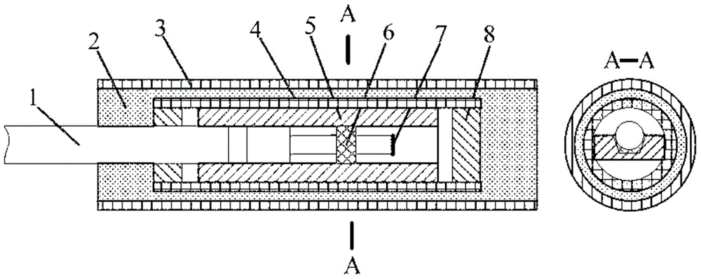
[0026] A packaging method for an optical fiber end reflector, the schematic diagram of the packaging structure of the optical fiber end reflector of the present invention is as follows figure 1 shown. In the figure, 1 is the optical fiber output end, 2 is the packaging glue (704 glue), 3 is the tempered glass tube, 4 is the quartz capillary tube, 5 is the quartz plate, 6 is the first fiber fixing glue (353ND glue), 7 is the anti-increasing Film, 8 is the second optical fiber fixing glue (353ND glue).

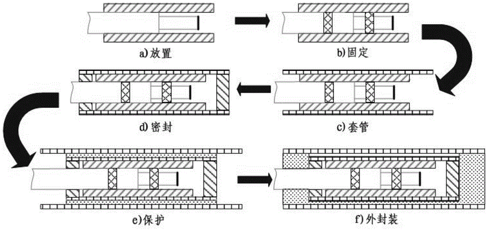
[0027] Process methods such as figure 2 Shown: The optical fiber end face reflector is set up from left to right at the fiber output end, bare fiber and anti-reflection coating. The length of the bare fiber part is 2-3mm, and the anti-reflection film is coated on the rightmost end of the bare fiber part, including the following step...


PUM


Abstract

The invention particularly relates to an optical fiber end surface reflecting mirror packaging method used for a reflecting type optical fiber current transformer. The method comprises the following steps of (1.1)arrangement: an optical fiber end surface reflecting mirror is horizontally arranged in a quartz plate groove; (1.2) fixing: a first type of optical fiber fixing glue is coated at the specific positions of the left of a reflection-increasing film and right of the left port of a quartz plate and then heated and cured and stands; (1.3) sleeving and sealing: the quartz plate is sleeved in a quartz capillary tube, and a second type of optical fiber fixing glue is coated at the two ports and then heated and cured and stands; (1.4) drying: the quartz capillary tube is arranged in a high-temperature drying box to be dried and then stands; (1.5) protection and external packaging: packaging glue is evenly coated on the surface of the capillary tube and then is externally sleeved by a toughened glass tube; (1.6) temperature cycling; and (1.7) use after standing. The structure obtained by the optical fiber end surface reflecting mirror packaging method has outstanding advantages that the structure is simple, the size is small, sealing performance is great, reliability is high and long-term use is stable.

Description

technical field [0001] The invention belongs to the technical field of packaging of optical fiber end reflectors, and in particular relates to a packaging method for optical fiber end reflectors used in reflective optical fiber current transformers. Background technique [0002] The reflective fiber optic current transformer is an ideal product to replace the traditional current transformer because of its good electrical insulation performance, excellent radiation resistance, extremely fast frequency response and high safety. Alternative status and broad market prospects. As the optical device and its installation parts of the outdoor part of the reflective fiber optic current transformer, the service life is required to be at least 10 years because it cannot be replaced frequently. Working in the harsh natural environment all the year round, it is disturbed by various external factors such as wind, sun, rain, lightning, etc., which puts forward high requirements for its lo...

Claims


Application Information

Patent Timeline
Patent Type & Authority Applications(China)
IPC IPC(8): G02B6/26
Inventor 杨怿吴衍记冯喆向强章敏段俊杰
Owner BEIJING AUTOMATION CONTROL EQUIP INST
Why Eureka
Try Eureka