Clutch device for retarder, vehicle including such a clutch device and method for engaging a retarder
A technology of clutch device and reducer, applied in clutches, fluid-driven clutches, mechanical-driven clutches, etc., can solve problems such as weight increase, and achieve the effects of weight reduction, increased service life and reliability, and reduced fuel consumption
- Summary
- Abstract
- Description
- Claims
- Application Information
AI Technical Summary
Problems solved by technology
Method used
Image

Examples
Embodiment Construction
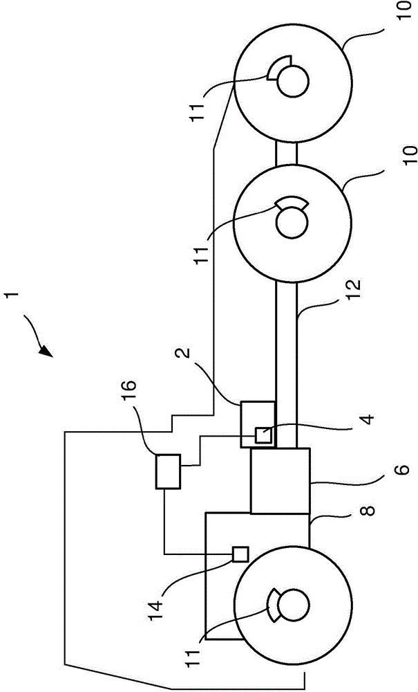
[0024] figure 1 A schematic side view of a vehicle 1 is shown, which is equipped with a reduction gear 2 which is connected and disconnected according to the invention to a clutch device 4 . The vehicle 1 is also equipped with a gearbox 6 connected to a combustion engine 8 which drives the drive wheels 10 of the vehicle 1 via the gearbox 6 and a conventional transmission comprising a propulsion shaft 12 and the like. The drive wheels 10 are equipped with wheel brakes 11 . The torque sensor 14 is provided on the combustion engine 8 to detect torque generated from the combustion engine 8 . The torque sensor 14 is connected to a control device 16 arranged to control the speed reducer 2 .
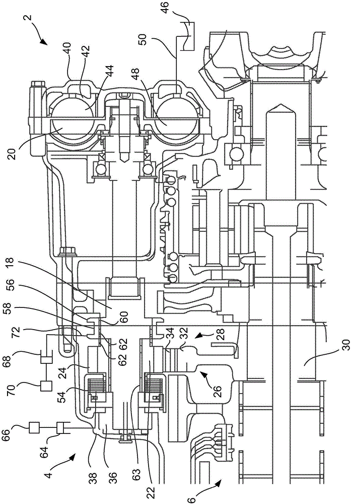
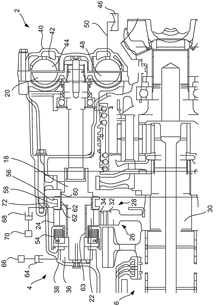
[0025] figure 2 A sectional view of the clutch device 4 for the reduction gear 2 in the disengaged state according to the first embodiment of the invention is shown. The clutch device 4 includes a first shaft 18 connected to a rotor 20 of the speed reducer 2 and a second shaft 22 arranged ...
PUM
 Abstract
Description
Claims
Application Information
 - Generate Ideas
- Intellectual Property
- Life Sciences
- Materials
- Tech Scout
- Unparalleled Data Quality
- Higher Quality Content
- 60% Fewer Hallucinations
Browse by: Latest US Patents, China's latest patents, Technical Efficacy Thesaurus, Application Domain, Technology Topic, Popular Technical Reports.
© 2025 PatSnap. All rights reserved.Legal|Privacy policy|Modern Slavery Act Transparency Statement|Sitemap|About US| Contact US: help@patsnap.com