
Construction method for pipe-following drilling micro pile of slewing drilling machine

A technology of pipe drilling and rotary drilling rig, which is applied in excavation, soil protection, foundation structure engineering, etc. It can solve problems such as subsidence not exceeding 15mm, uplift and deformation of subgrade soil, poor foundation treatment effect, etc., and achieve construction technology Easy, eliminate hole collapse and improve pile quality

Inactive Publication Date: 2015-10-07
HUBEI UNIV OF TECH
View PDF3 Cites 2 Cited by
  • Summary
  • Abstract
  • Description
  • Claims
  • Application Information

AI Technical Summary

Problems solved by technology

Grouting reinforcement is to inject cement mortar, chemical grout and other materials into the diseased foundation through pressure grouting to improve the mechanical properties of the foundation soil. If the grouting pressure is too small, the foundation treatment effect will be poor, and if the grouting pressure is too high Sometimes it will lead to a certain degree of uplift deformation of the subgrade soil, which is difficult to achieve the expected treatment effect
The settlement control standard of the high-speed railway is extremely strict, requiring that the post-construction settlement of the subgrade should not exceed 15mm, which is equivalent to the control requirement of zero settlement. Therefore, ordinary railway subgrade disease control measures cannot be directly applied to high-speed railway subgrade disease control

Method used


Image

  • Construction method for pipe-following drilling micro pile of slewing drilling machine
  • Construction method for pipe-following drilling micro pile of slewing drilling machine
  • Construction method for pipe-following drilling micro pile of slewing drilling machine

Examples


Embodiment Construction

[0025] Describe the present invention in detail below with reference to accompanying drawing:

[0026] Concrete steps of the present invention are as follows:

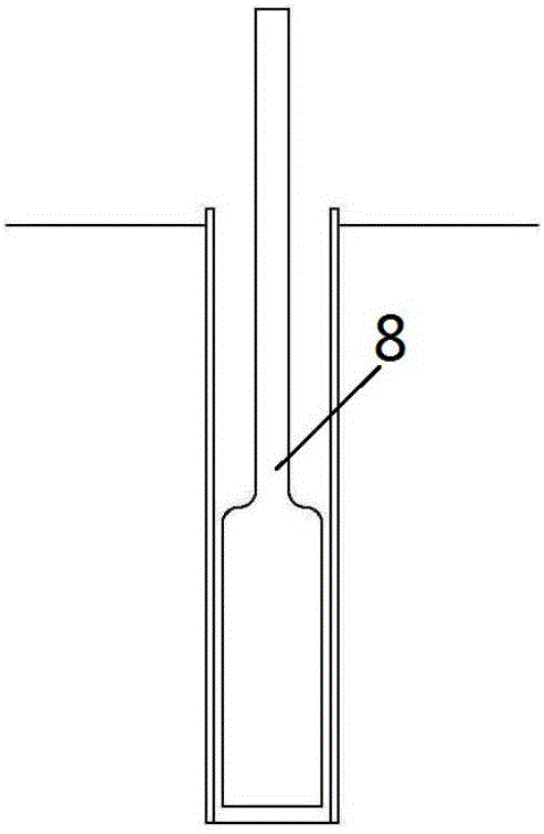
[0027] 1) Install the drilling rig in place on the working platform, and the drilling rig adopts a rotary drilling rig. Adjust drill rod, drill bit position, angle and design parameter to be consistent; After getting ready, start drilling with rotary drill drill rod, core pipe and drill bit 8 (see figure 1 );

[0028] 2) Set up a water pool near the drilling rig. The water pool needs to be plastered with cement mortar or other effective anti-seepage measures to avoid the impact of circulating water seepage on the foundation soil. The positive circulation method is used to cool the drill bit and remove slag with circulating water; each time the footage is 0.8-1.2m, the core tube is used to take the soil core and core out of the borehole.

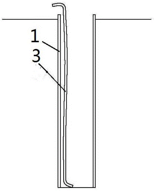
[0029] 3) With the drilling of the drilling rig, every time 0.25-0.5m is drill...


PUM

PropertyMeasurementUnit
Diameteraaaaaaaaaa
Diameteraaaaaaaaaa

Abstract

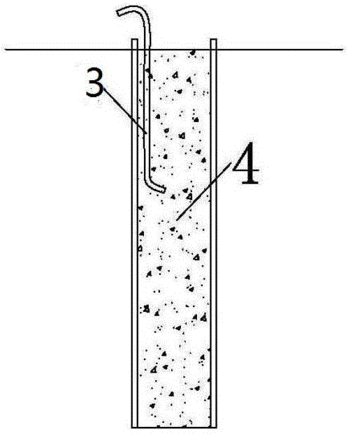
The invention discloses a construction method for a pipe-following drilling micro pile of a slewing drilling machine. The drilling machine is installed in place, and the orientations and angles of a drill pipe and a drill bit are adjusted to be uniform with design parameters; after preparation, drilling starts to be performed; a direct cycle method is adopted, and circulating water is utilized for cooling the drill bit and removing slag; a wall-protecting steel casing pipe follows and is pressed synchronously every time drilling is performed by 0.25 m-0.5 m, and the distance between the wall-protecting steel casing pipe and the bottom of a hole is smaller than or equal to 0.5 m; every time drilling is performed by 1 m-2 m, the angle of the drill pipe is checked one time; after reaching a designed depth, the drill pipe and a drilling tool are taken out; fine aggregate concrete or cement mortar is injected into the wall-protecting steel casing pipe; after the concrete or the cement mortar is solidified, the pipe-following drilling micro pile for reinforcing roadbeds of existing high-speed railways is formed. Soil body disturbance of the roadbed can be avoided to the maximum degree, and roadbed additive deformation caused by regulation of project construction is prevented. Construction can be performed under the driving conditions of the existing high-speed railways, and normal operation of existing lines is not affected; the construction method is suitable for performing disease regulation on roadbed deformation occurring on the existing high-speed railways.

Description

technical field [0001] The invention relates to the technical field of existing high-speed railway embankment disease reinforcement, in particular to a construction method for drilling miniature piles with a rotary drilling rig and a pipe. Background technique [0002] At present, there are nearly 10,000 kilometers of high-speed railways in operation in my country. Affected by the natural environment, roadbed diseases occur, and most of them are roadbed deformation diseases. At present, roadbed diseases of ordinary railways are often treated by means of reinforced piles and grouting. There are two methods of reinforced piles: cast-in-place piles and prefabricated piles: cast-in-place piles need to be pre-formed, and are made by setting steel cages and pouring concrete. During the construction process, the subgrade soil will inevitably cause a certain degree of subsidence and deformation ; The prefabricated piles need to be penetrated into the foundation by static pressure o...

Claims


Application Information

Patent Timeline
IPC IPC(8): E02D3/08E01B2/00E02D17/20E02D17/04
Inventor 杨艳霜黄彩萍张帆万娟
Owner HUBEI UNIV OF TECH
Learn More