Oval tube type efficient cooling fin
A heat sink, ellipse technology, applied in the field of elliptical tube type high-efficiency heat sink, can solve the problems of short service life, large wind resistance pressure drop, etc., and achieve the effects of wind resistance pressure reduction, low wind resistance pressure drop, and large heat dissipation area.
- Summary
- Abstract
- Description
- Claims
- Application Information
AI Technical Summary
Problems solved by technology
Method used
Image

Examples
Embodiment 1
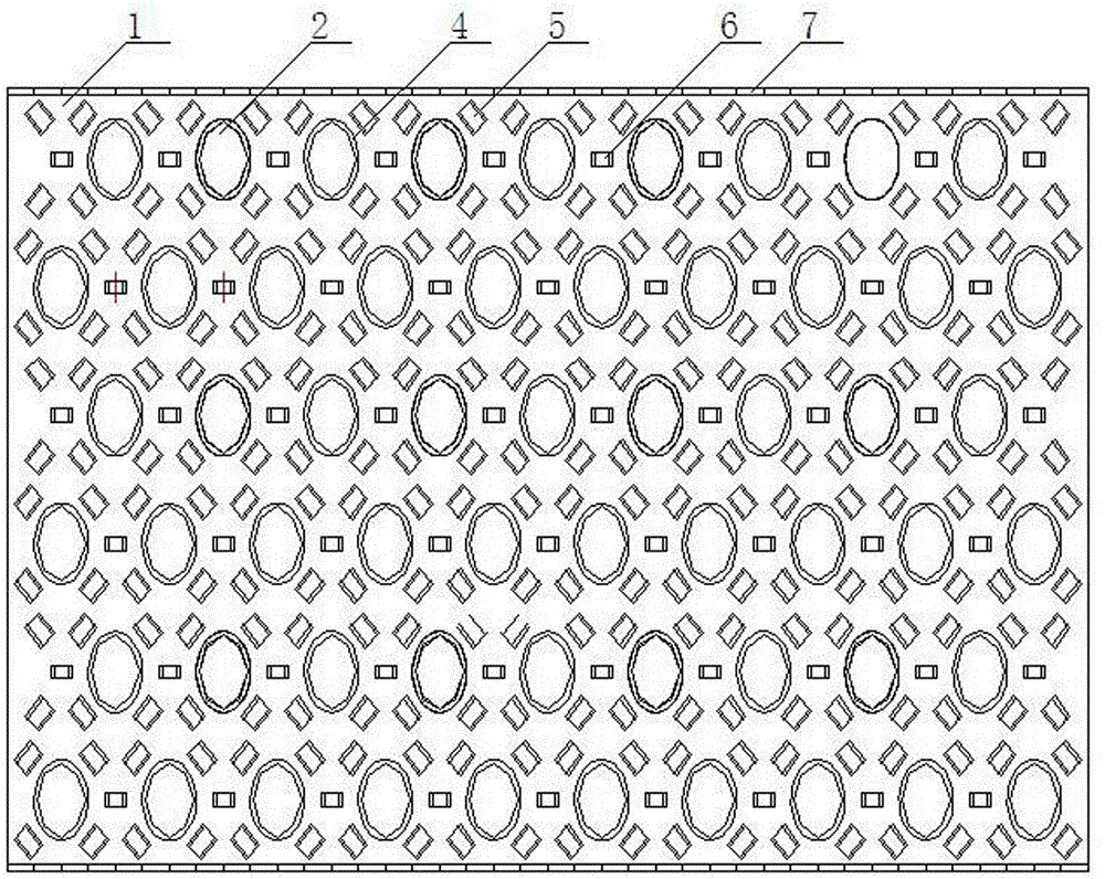
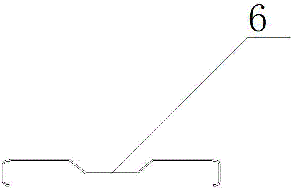
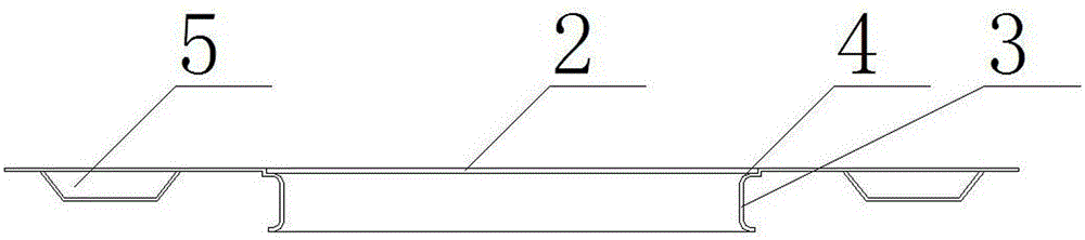
[0036] As shown in the figure, an elliptical tube-type high-efficiency heat sink includes a sheet body 1, an oval hole 2, a ring-shaped arch bridge punching hole 5, and a square arch bridge punching hole 6. The sheet body 1 is punched integrally. A plurality of elliptical holes 2 are installed on the sheet body 1. The elliptical hole 2 has two elliptical flanges 3, an elliptical groove 4 is arranged above the elliptical hole 2, and an annular arch bridge punching hole 5 is arranged around the elliptical hole 2. The elliptical hole 2 A square bridge-shaped punching hole 6 is set between the adjacent oval hole 2, and the sheet body 1 is provided with a corrugated edge 7 longitudinally. The sheet body 1 is made of T2 copper or TP1 copper or L2 aluminum, and is installed on the cooling core of the cooler. used in the group.
[0037] The arrangement of the elliptical holes 2 is that the hole pitch is 32mm, and the row pitch is 38mm.
[0038] The oval hole on the sheet has a ...
Embodiment 2
[0045] As shown in the figure, an elliptical tube-type high-efficiency heat sink includes a sheet body 1, an oval hole 2, a ring-shaped arch bridge punching hole 5, and a square arch bridge punching hole 6. The sheet body 1 is punched integrally. A plurality of elliptical holes 2 are installed on the sheet body 1. The elliptical hole 2 has two elliptical flanges 3, an elliptical groove 4 is arranged above the elliptical hole 2, and an annular arch bridge punching hole 5 is arranged around the elliptical hole 2. The elliptical hole 2 A square bridge-shaped punching hole 6 is set between the adjacent oval hole 2, and the sheet body 1 is provided with a corrugated edge 7 longitudinally. The sheet body 1 is made of T2 copper or TP1 copper, and is installed in the cooling core group of the cooler for use. .
[0046] The hole spacing of the arrangement of the oval holes 2 is 32 mm, and the row spacing is 38 mm.
[0047] The oval hole on the sheet has a major semi-axis of 12.1...
Embodiment 3
[0055] As shown in the figure, an elliptical tube-type high-efficiency heat sink includes a sheet body 1, an oval hole 2, a ring-shaped arch bridge punching hole 5, and a square arch bridge punching hole 6. The sheet body 1 is punched integrally. A plurality of elliptical holes 2 are installed on the sheet body 1. The elliptical hole 2 has two elliptical flanges 3, an elliptical groove 4 is arranged above the elliptical hole 2, and an annular arch bridge punching hole 5 is arranged around the elliptical hole 2. The described A square bridge-shaped punching hole 6 is set between the oval hole 2 and the adjacent oval hole. The sheet body 1 is provided with corrugated hem 7 longitudinally. The sheet body 1 is made of L2 aluminum and installed in the cooling core group of the cooler.
[0056] The hole spacing of the arrangement of the oval holes 2 is 32 mm, and the row spacing is 38 mm.
[0057] The oval hole on the sheet has a major semi-axis of 12.15 mm and a minor semi-ax...
PUM
| Property | Measurement | Unit |
|---|---|---|
| Flange height | aaaaa | aaaaa |
| Semi-major axis | aaaaa | aaaaa |
| Depth | aaaaa | aaaaa |
Abstract
Description
Claims
Application Information
 - R&D Engineer
- R&D Manager
- IP Professional
- Industry Leading Data Capabilities
- Powerful AI technology
- Patent DNA Extraction
Browse by: Latest US Patents, China's latest patents, Technical Efficacy Thesaurus, Application Domain, Technology Topic.
© 2024 PatSnap. All rights reserved.Legal|Privacy policy|Modern Slavery Act Transparency Statement|Sitemap