
Automatic photosynthetic photon sensor detection and calibration system and method

An automatic detection and sensor technology, applied in photometry, optical radiation measurement, instruments, etc., can solve the problems of inaccurate calibration, sensor accuracy deviation, sensor drift, etc., to achieve high flexibility, improve calibration accuracy and efficiency. Effect

Active Publication Date: 2015-10-07
BEIJING RES CENT FOR INFORMATION TECH & AGRI
View PDF6 Cites 6 Cited by
  • Summary
  • Abstract
  • Description
  • Claims
  • Application Information

AI Technical Summary

Problems solved by technology

The reference equipment uses imported optical quantum sensors. In the initial stage, due to the high precision of imported optical quantum sensors, better accuracy can be achieved, but the sensor will drift after one or two years, resulting in inaccurate overall proofreading
[0008] Using the calculation method to obtain the current light quantum density, it is necessary to know the accuracy, dimension, altitude, weather and other conditions of the measurement point to roughly obtain the current light quantum flux, which is very difficult in the actual operation process, and the accuracy of the sensor after calibration is biased

Method used


Image

  • Automatic photosynthetic photon sensor detection and calibration system and method
  • Automatic photosynthetic photon sensor detection and calibration system and method
  • Automatic photosynthetic photon sensor detection and calibration system and method

Examples


Embodiment Construction

[0072] In order to make the objectives, technical solutions and advantages of the embodiments of the present invention clearer, the following will clearly and completely describe the technical solutions in the embodiments of the present invention in conjunction with the accompanying drawings in the embodiments of the present invention. Obviously, the described embodiments It is only a part of the embodiments of the present invention, not all the embodiments. Based on the embodiments of the present invention, all other embodiments obtained by those of ordinary skill in the art without creative work shall fall within the protection scope of the present invention.

[0073] The existing proofreading programs include:

[0074] (1) Standard illuminance light source calibration plan

[0075] Due to the low cost of illuminance sensor application and proofreading related products, it has a large market foundation. At present, its own proofreading specifications have been formed. The Illumina...


PUM


Abstract

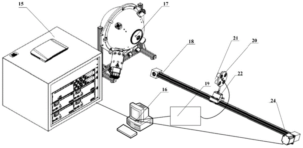
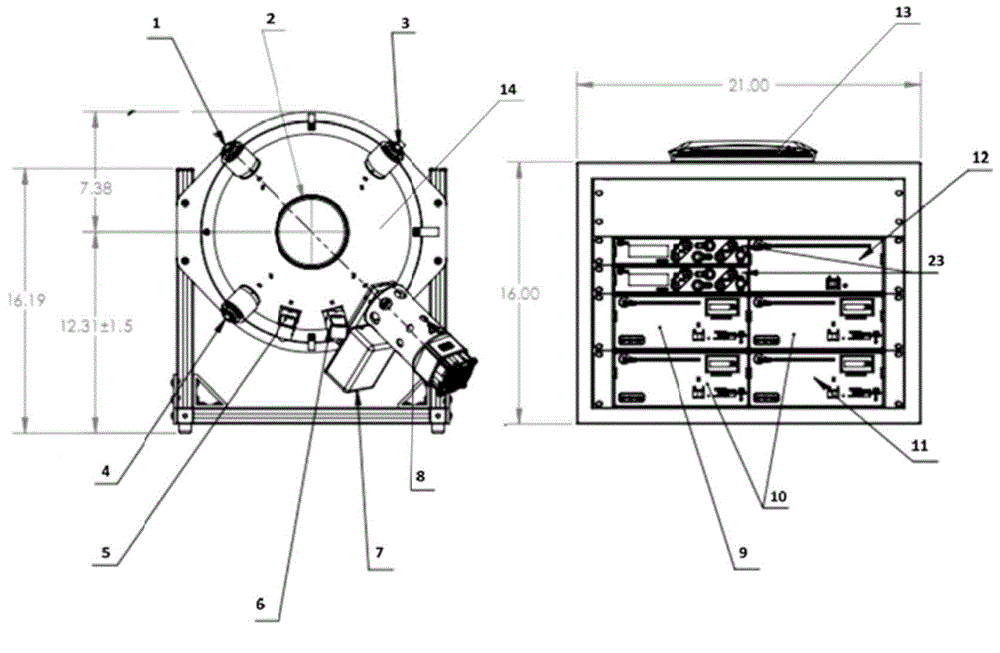
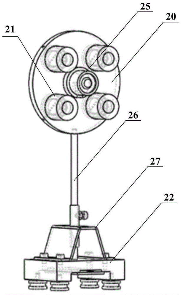
The invention provides an automatic photosynthetic photon sensor detection and calibration system and a method. The system comprises a uniform light source system, a mobile optical platform, a spectral radiometer and an upper computer, wherein the uniform light source system comprises an optical integrating sphere, a standard light source, an adjustable light source, an electronic attenuator connected with the adjustable light source, a light detector and a power supply cabinet; the power supply cabinet comprises a power supply connected with the standard light source and the adjustable light source, an attenuator controller connected with the electronic attenuator and a reading meter connected with the light detector; the power supply, the attenuator controller and the reading meter are all connected with the upper computer; the mobile optical platform comprises an optical guide rail, a stepper motor connected with the optical guide rail and the upper computer respectively, a movable base, and a calibration chassis arranged on the movable base via a clamping seat and a supporting rod; the center of the calibration chassis coaxial with the center of a light outlet is provided with a standard probe connected with the upper computer via the spectral radiometer; and calibrated sensors connected with the upper computer are uniformly arranged in a preset radius region of the center of the calibration chassis. Full range of the calibrated sensor is automatically calibrated, and the calibration precision and the efficiency are improved.

Description

Technical field [0001] The invention relates to the technical field of light quantum sensor verification, in particular to a photosynthetically active light quantum sensor automatic detection and proofreading system and method. Background technique [0002] The theory of quantum mechanics confirms that the energy of solar radiation is carried by a single photon, and the number of photons is used to define the radiation intensity. Commonly used photon density, that is, the number of photons that reach or pass through a unit area per unit time, in mol / (m2s) (1mol=6.02257*1023 photons). The photon density of the radiation wave effective for plant photosynthesis is called photosynthetic photon flux density (PPFD), sometimes also referred to as photosynthetic photon flux density (PPF). Currently, photosynthetically active radiation sensors are often used instead, and the unit is W / m 2 , Measure the energy of photosynthetic light at 400-700nm. [0003] PPFD is not only a key factor in...

Claims


Application Information

Patent Timeline
IPC IPC(8): G01J1/00
Inventor 张馨张石锐田宏武郭瑞李文龙吴文彪乔晓军
Owner BEIJING RES CENT FOR INFORMATION TECH & AGRI
Learn More