Supercharge Your Innovation With Domain-Expert AI Agents!

A visual fiber assembly device

An assembly device and optical fiber technology, which is applied in the direction of light guides, optics, optical components, etc., can solve the problems of increased processing costs, high processing and manufacturing costs, and damage to optical fiber end faces. The effect of assembly contact

Active Publication Date: 2016-09-14
GUANGXUN SCI & TECH WUHAN
View PDF4 Cites 0 Cited by
  • Summary
  • Abstract
  • Description
  • Claims
  • Application Information

AI Technical Summary

Problems solved by technology

[0007]Because the diameter of the assembly hole of the optical fiber assembly is very small, the traditional method of relying on manual assembly is easy to cause damage to the end face of the optical fiber due to the misalignment of the assembler during the operation
At present, many optical fibers have processed lenses and coatings on the end faces, and the processing and manufacturing costs are very high, which will result in increased defect rates and disadvantages in processing costs

Method used


Image

  • A visual fiber assembly device
  • A visual fiber assembly device
  • A visual fiber assembly device

Examples


Embodiment Construction

[0029] The present invention will be further described below in conjunction with the embodiments shown in the accompanying drawings.

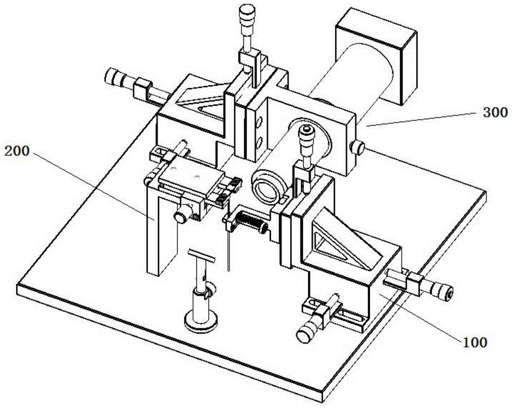
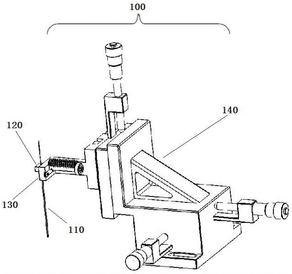
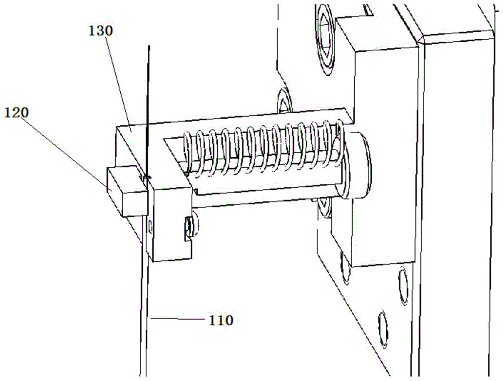
[0030] A visual optical fiber assembly device includes a visual imaging system, an optical fiber clamping system, and an assembly clamping system, wherein the visual imaging system is provided with a microscope device, a CCD imaging receiving device, a mirror reflection imaging device, and an XYZ three-dimensional adjustment frame. The fiber clamping system includes a fiber placement trough, a fiber block and an XYZ three-dimensional adjustment frame. The assembly clamping system includes assembly placement blocks, block adjustment knobs and system brackets.

[0031] In the following specification, in order to briefly and clearly illustrate embodiments of the invention, the drawings may not be to scale and some features may be labeled in a schematic manner only.

[0032] attached figure 1 It is a schematic diagram of a specific embodiment of ...


PUM


Abstract

The invention provides a visual optical fiber assembling device. The visual optical fiber assembling device comprises a visual imaging system, an optical fiber clamping system and an assembly part clamping system. Good clamping of an optical fiber and an assembly part and assembling position adjustment are achieved through the optical fiber clamping system and the assembly part clamping system. The assembling precision of the optical fiber and the assembly part during the assembling process is monitored and ensured through the visual imaging system. The problem of contact of an end face of an optical fiber and an assembly part during the manual assembling process is avoided effectively, and the purpose of lowering the production reject ratio can be achieved. Through simultaneous clamping of multiple optical fibers and multiple assembly parts and introduction of an electric platform to replace an X, Y, Z-three dimensional adjusting rack, and with cooperation of external display monitoring, automatic assembling of optical fiber elements can be achieved and the production efficiency is raised greatly.

Description

technical field [0001] The invention belongs to the technical field of optical fiber communication, in particular to a visual optical fiber assembly device. Background technique [0002] Optical signal transmission has the advantages of fast speed and low interference, so it is widely used in signal transmission between electronic devices. Optical fiber components used for optical signal transmission are an important part of the entire signal transmission system. [0003] Fiber optic components are composed of optical fibers and various tubular assemblies with inner holes according to different applications. [0004] Optical fiber is the abbreviation of optical fiber, which is a light transmission tool achieved by the principle of total reflection of light in fibers made of glass or plastic. Optical fiber is a very pure glass fiber. The main component of the core material is doped SiO2 with a content of 99.999%, and the rest is a very small amount of dopant such as GeO2 t...

Claims


Application Information

Patent Timeline
Patent Type & Authority Patents(China)
IPC IPC(8): G02B6/38
CPCG02B6/3898
Inventor 曾乾徐红春宋小平
Owner GUANGXUN SCI & TECH WUHAN
Features
  • R&D
  • Intellectual Property
  • Life Sciences
  • Materials
  • Tech Scout
  • Unparalleled Data Quality
  • Higher Quality Content
  • 60% Fewer Hallucinations
Learn More