Split-type light-guide key switch and mechanical keyboard

A split type, button technology, applied in the direction of electric switches, legends, electrical components, etc., can solve the problems of limited service life, troublesome disassembly and maintenance, difficult to control, etc., to reduce costs and process requirements, improve accuracy and service life, convenient The effect of maintenance and repair

Active Publication Date: 2015-10-07
深圳芯合云电子科技有限公司
View PDF5 Cites 11 Cited by
  • Summary
  • Abstract
  • Description
  • Claims
  • Application Information

AI Technical Summary

Problems solved by technology

With this scheme, the metal contacts of the mechanical switch are easily damaged, because in the process of pressing the button, the elasticity of the dynamic pressure plate will be greatly different from the original state with the increase in the number of uses, which will easily cause the metal contacts to fail. Sensitive or non-conductive state, limited service life, causing trouble to users
In addition, in the traditional mechanical keyboard, the optical crystal transmitting and receiving device is set in the key switch, the bottom pins are welded on the PCB board, and then the key switch is snapped into the card slot, and finally the fixed column on the rotating iron plate is fixed to the key switch. The PCB board is fixed to the iron plate, which makes it very troublesome to disassemble and repair once a button is damaged. Not only need to unscrew the fixing column, but also need to unplug the optical crystal receiving device and transmitting device from the PCB board. It is very difficult to handle, and it is easy to cause damage to the keyboard. At the same time, the conduction accuracy of this type of keyboard is limited by the distance between the PCB board and the iron plate, so it is not easy to control; in addition, this type of keyboard is not conducive to large-scale industrial production.

Method used


Image

  • Split-type light-guide key switch and mechanical keyboard
  • Split-type light-guide key switch and mechanical keyboard
  • Split-type light-guide key switch and mechanical keyboard

Examples


Embodiment 1

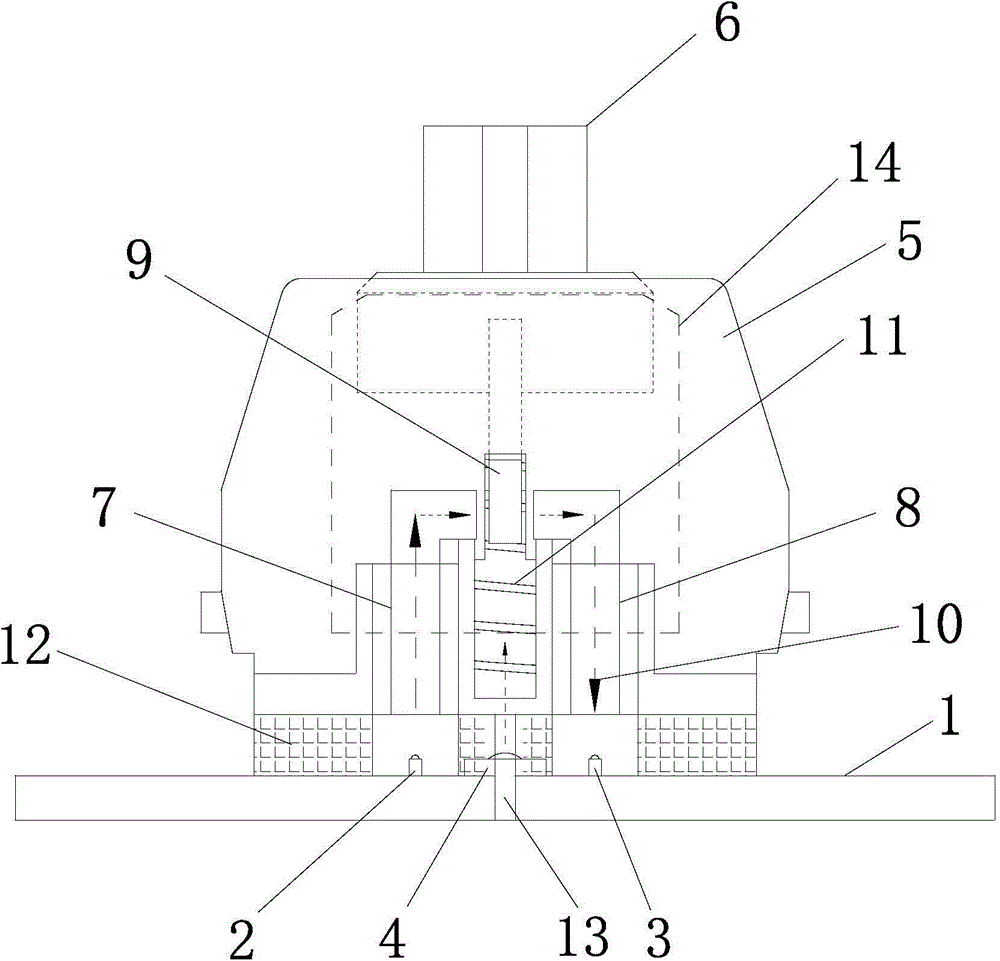
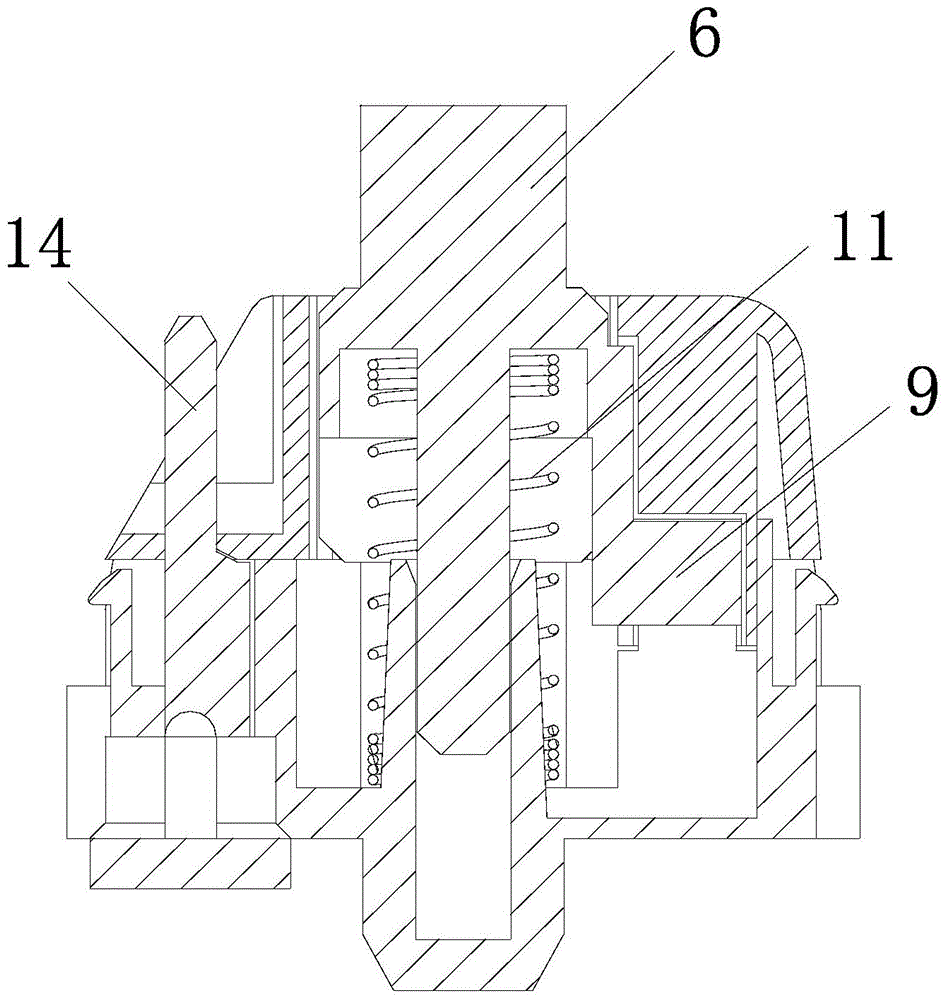
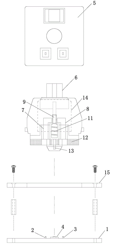
[0037] Such as Figure 1 ~ Figure 3As shown, the split-type photoconductive key switch of this embodiment includes a key switch body, an optical crystal emitting device 2 arranged on a PCB board 1, an optical crystal receiving device 3 and an LED backlight 4, and the key switch body includes a housing 5 And the handle 6 arranged on the housing 5, the optical crystal emitting device 2 and the optical crystal receiving device 3 are separated by the first light blocking device; the top of the optical crystal emitting device 2 is provided with a first light guide body 7, the top of the optical crystal receiving device 3 is provided with a second light guide 8, and the handle 6 is provided with a second light blocking device 9; the top of the first light guide 7 is bent to the right The top of the second light guide body 8 is bent to the left, and the part between the part bent to the right at the top of the first light guide body 7 and the part bent to the left at the top of the s...

Embodiment 2

[0047] Such as Figure 5 As shown, the main features of this embodiment are: the first light blocking device is a sealing ring 12, and the sealing ring 12 can separate the optical crystal emitting device 2 from the optical crystal receiving device 3, and can prevent the optical crystal from The transmitting device 2 and the optical crystal receiving device 3 are in contact with the outside world, and play the roles of light blocking and dustproof at the same time. All the other structural features are the same as in Example 1.

Embodiment 3

[0049] Such as Figure 6 As shown, the split-type photoconductive key switch of this embodiment includes a key switch body, an optical crystal emitting device 2 arranged on a PCB board 1, an optical crystal receiving device 3 and an LED backlight 4, and the key switch body includes a housing 5 And the handle 6 arranged on the housing 5, the optical crystal emitting device 2 and the optical crystal receiving device 3 are separated by the first light blocking device; the top of the optical crystal emitting device 2 is provided with a first light guide body 7, the top of the optical crystal receiving device 3 is provided with a second light guide 8, the handle 6 is provided with a second light blocking device 9, and the first light guide 7 is provided with an obliquely arranged The first light reflector 16, the second light guide body 8 is provided with a second light reflector 17 arranged obliquely; the optical signal emitted by the optical crystal emitting device 2, after being...


PUM


Abstract

The invention discloses a split-type light-guide key switch and mechanical keyboard. The key switch comprises a key switch body, an optical crystal emitter device and an optical crystal receiver device, wherein the optical crystal emitter device and the optical crystal receiver device are arranged on a PCB. The key switch body comprises a housing and a press handle arranged on the housing. The optical crystal emitter device and the optical crystal receiver device are separated by a first light baffle device. A first light guider is arranged above the optical crystal emitter device. A second light guider is arranged above the optical crystal receiver device. Optical signals emitted by the optical crystal emitter device are transmitted back to the optical crystal receiver device through the first light guider and the second light guider. The press handle is provided with a second light baffle device for baffling the optical signals transmitted from the first light guider to the second light guider. Through the light guiders, not only the transmission stability of the optical signals is improved, but also cost and process requirement of the key switch are reduced, and meanwhile, precision and the service life of the mechanical keyboard are greatly improved.

Description

technical field [0001] The invention relates to a key switch and a mechanical keyboard, in particular to a split-type photoconductive key switch and a mechanical keyboard, belonging to the research field of mechanical keyboards. Background technique [0002] A mechanical keyboard is a common type of keyboard in which each key has an individual switch to control the closure. As a representative of high-end products, the mechanical keyboard has been welcomed by more and more computer users and game players. The switch generally used is a mechanical key switch of the metal material contact type. This switch is set in the casing Whether the metal material contacts of the static pressure plate and the dynamic pressure plate are in contact with each other to realize the on-off of the switch, during the displacement process of pressing the mechanical switch handle, the metal material contacts on the dynamic pressure plate and the metal material of the static pressure plate The mat...

Claims


Application Information

Patent Timeline
Patent Type & Authority Applications(China)
IPC IPC(8): H01H13/83
CPCH01H13/83H01H2219/014
Inventor 郝小妮张益乐
Owner 深圳芯合云电子科技有限公司
Why Eureka
Try Eureka