Smart lock and power supply system thereof

A power supply system and smart lock technology, applied in the field of smart locks, can solve the problems of high power consumption and short battery life of smart locks, and achieve the effects of prolonging life, reducing power consumption, and long service life

Active Publication Date: 2015-10-07
北京摇光智能科技有限公司
View PDF6 Cites 13 Cited by
  • Summary
  • Abstract
  • Description
  • Claims
  • Application Information

AI Technical Summary

Problems solved by technology

[0009] The purpose of the present invention is to provide an intelligent lock, which can generate electric energy through manual power generation or pressing power generation, and has a power supply system that can automatica

Method used


Image

  • Smart lock and power supply system thereof
  • Smart lock and power supply system thereof

Examples


Embodiment 1

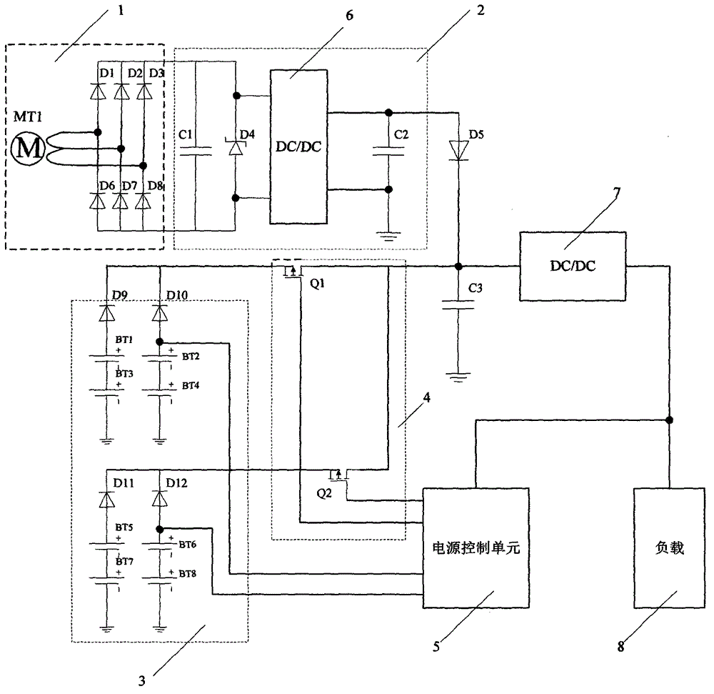
[0035] See attached figure 1 , the smart lock power supply system of the present invention includes an energy conversion unit 1 , a charging and discharging unit 2 , a battery pack unit 3 , a battery pack power supply switching unit 4 , a power control unit 5 and a DC-DC conversion device 7 .

[0036]The energy conversion unit 1 is an energy conversion unit capable of converting mechanical energy into DC electric energy. In this embodiment, a hand-operated power generator is used to drive the motor, and then it is realized through a rectification circuit. Specifically, the manual power generation device installs a concentric gear on the shaft of the handle (or rotating mechanism) of the smart lock body, and the concentric gear drives three or four gears in sequence, amplifies the linear velocity of the gear edge step by step, and finally drives motor. The motor can be a three-phase AC motor, a two-phase AC motor, or a DC motor. In this embodiment, a three-phase AC motor MT1 i...

Embodiment 2

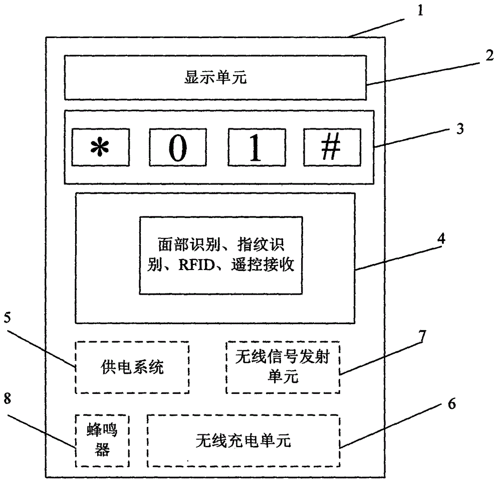
[0048] Participate in figure 2 , another embodiment of the present invention is a smart lock with manual power generation, including a lock body 1, and a display unit 2 is arranged on the lock body 1 to display the switch state of the smart lock and the battery power condition; a password button is provided 3. It is used to input the unlock password, and the input password signal is analyzed and processed to control the lock cylinder driving mechanism to control whether the lock cylinder is opened or not. The password button 3 is different from the traditional 0-9 button settings, and a two-key keyboard is used. Setting, that is: firstly, various types of passwords are mapped to binary sequences through a certain type of algorithm. This input method reduces the number of keys. At the same time, skilled and technical personnel can set *, # and other function keys on the password key 3 according to actual design needs, so as to expand the required functions.

[0049] An inform...


PUM


Abstract

The present invention puts forward a smart lock and a power supply system thereof. The power supply system can supply power through two modes. One mode is characterized in that electric energy is stored on a capacitor C2 after being generated through a hand-operated power generation apparatus and via an energy conversion unit, so as to supply power to a subsequent load. The other mode is characterized in that a power supply control unit selects one pack from battery packs for supplying power to a load by controlling transistor switches Q1 and Q2. When a voltage outputted by the power generation apparatus is higher than a certain threshold value, the power supply system automatically gives priority in use of the electric energy provided by the power generation apparatus. According to the smart lock, a traditional keyboard system is changed into a two-key keyboard system, so that passwords can be entered conveniently in a dark environment without an illumination circuit, thereby greatly reducing power consumption. Through adoption of the smart lock and the power supply system in the present invention, power supply efficiency is improved, power supply time is prolonged, and the system can still continue working through the power generation apparatus in the case that the smart lock is completely out of power, thus the biggest usage inconvenience problem of an electronic smart lock is solved, and the practical value of the smart lock is greatly improved.

Description

technical field [0001] The invention relates to an intelligent lock, in particular to an intelligent power supply system capable of automatically switching power supply states in the intelligent lock. Background technique [0002] Smart locks refer to locks that are more intelligent in terms of user identification, security, and management, which are different from traditional mechanical locks. [0003] Smart locks are roughly divided into two categories in terms of identity verification technology. The first category is based on biometric and image recognition technology solutions, such as: fingerprints, face recognition, this solution usually consumes a lot of power, and because it involves image Identification, the success rate cannot be 100%. The second largest type of scheme is to adopt a digital key scheme, but the unlocker needs to hold a certificate containing the relevant key (usually some smart terminals, such as mobile phones, remote controls, IC cards, etc.). ...

Claims


Application Information

Patent Timeline
IPC IPC(8): H02J7/32H02J7/36G07C9/00
Inventor 余绵梓王作苍程峰
Owner 北京摇光智能科技有限公司
Why Eureka
Try Eureka