System and method for producing optical display devices

A technology of optical display and production system, applied in the direction of optics, nonlinear optics, layered products, etc., can solve the problems that hinder the miniaturization of equipment, achieve the effects of suppressing warpage, expanding miniaturization, and suppressing dimensional deviation

Active Publication Date: 2015-10-07
SUMITOMO CHEM CO LTD
View PDF9 Cites 5 Cited by
  • Summary
  • Abstract
  • Description
  • Claims
  • Application Information

AI Technical Summary

Problems solved by technology

[0009] However, in the above-mentioned conventional configuration, the plate sheet slightly larger than the display area is cut out in consideration of the dimensional deviations of the liquid crystal panel and the plate sheet, as we

Method used


Image

  • System and method for producing optical display devices
  • System and method for producing optical display devices
  • System and method for producing optical display devices

Examples


no. 2 approach

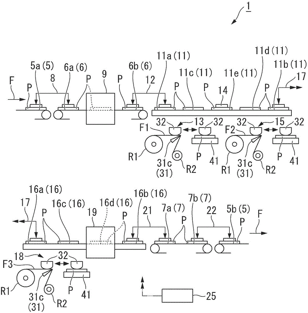
[0143] Next, the structure of the film bonding system which concerns on 2nd Embodiment is demonstrated. Figure 8 It is a schematic configuration diagram of the film bonding system 2 of this embodiment. exist Figure 8 In , for convenience of illustration, the film bonding system 2 is divided into upper and lower two stages and described. Hereinafter, the same reference numerals are assigned to the same components as those of the first embodiment, and detailed description thereof will be omitted.

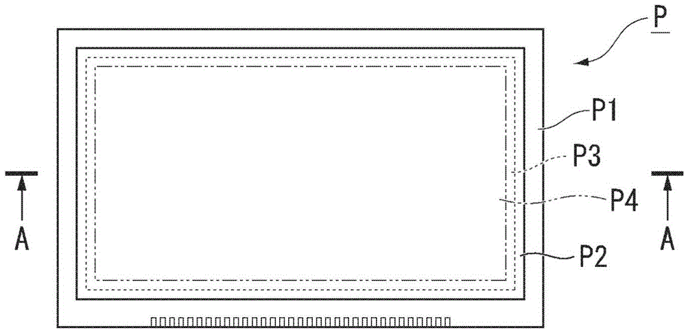
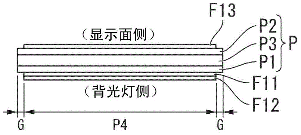
[0144] In 1st Embodiment, the case where the width and length of the optical member F1X bonded by the bonding head 32 and the same width and length as the display area P4 of liquid crystal panel P are mentioned as an example. On the other hand, in this embodiment, a cutting device is provided to cut off the remaining part of the plate sheet after bonding the plate sheet larger than the display area P4 (with a large width and length) to the liquid crystal panel P. There is a big d...


PUM


Abstract

This system for producing optical display devices is provided with a laminating device which, for a plurality of optical display components (P) transported on a line, unwinds a belt-shaped optical member sheet (F1) having a width corresponding to the display area of the optical display components from a whole-sheet roll (R1), and, while so doing, cuts the optical member sheet to a length corresponding to the display region to obtain an optical member (F11), and then laminates the optical member onto the optical display component. The laminating device has: a laminating head (32) whereby the optical member held in place by being pasted to an arc-shaped holding surface (32a) is laminated onto the optical display component; a movement device (44) for moving the laminating head and the optical display component relative to each other during lamination of the optical member; and a drive device (42) for driving the laminating head so that the laminating head is tilted along the curve of the holding surface during lamination of the optical member, the laminating head pressing the optical member against the optical display component.

Description

technical field [0001] The invention relates to a production system and production method of optical display devices such as liquid crystal displays. [0002] This application claims priority based on Japanese Patent Application No. 2013-058977 for which it applied in Japan on March 21, 2013, and Japanese Patent Application No. 2013-104149 for which it applied in Japan on May 16, 2013, and uses the content here. Background technique [0003] In the past, in the production system of optical display devices such as liquid crystal displays, optical members such as polarizing plates bonded to liquid crystal panels (optical display components) sometimes had to be cut out from long films to match the size of the display area of ​​the liquid crystal panel. , Packed and transported to another production line, and bonded to a liquid crystal panel (for example, refer to Patent Document 1). [0004] prior art literature [0005] patent documents [0006] Patent Document 1: JP Unexam...

Claims


Application Information

Patent Timeline
IPC IPC(8): G09F9/00G02F1/1335
CPCG02F1/1303B32B2457/20
Inventor 田中大充岸崎和范
Owner SUMITOMO CHEM CO LTD
Why Eureka
Try Eureka