Fluorescent-light-source device

A light source device, fluorescent technology, applied in the direction of light source, electric light source, projection device, etc., can solve problems such as failure, high luminous efficiency, and inability to obtain, and achieve the effect of easy formation and high luminous efficiency

Inactive Publication Date: 2015-10-07
USHIO DENKI KK
View PDF8 Cites 10 Cited by
  • Summary
  • Abstract
  • Description
  • Claims
  • Application Information

AI Technical Summary

Problems solved by technology

[0003] However, the fluorescent light source device equipped with a rotating wheel has the following problems: the engine parts that rotate and drive the rotating wheel are prone to deterioration and failure, and the configuration of the driving system itself is complicated.
[0005] However, such a fluorescent light source device has the following problem: when the excitation light is irradiated to the fluorescent member 41, the excitation light is scattered backward on the surface of the fluorescent member 41, so the excitation light does not sufficiently enter the fluorescent member 41. , as a result, high luminous efficiency cannot be obtained
Thus, it can be seen that since the fluorescence generated inside the wavelength conversion member cannot be efficiently extracted from the fluorescence emission surface, the fluorescence cannot be effectively used and high luminous efficiency cannot be obtained.
The cause of such a problem is that most of the fluorescence generated inside the wavelength conversion member is totally reflected by critical angle reflection on the fluorescence exit surface.

Method used


Image

  • Fluorescent-light-source device
  • Fluorescent-light-source device
  • Fluorescent-light-source device

Examples


experiment example 1

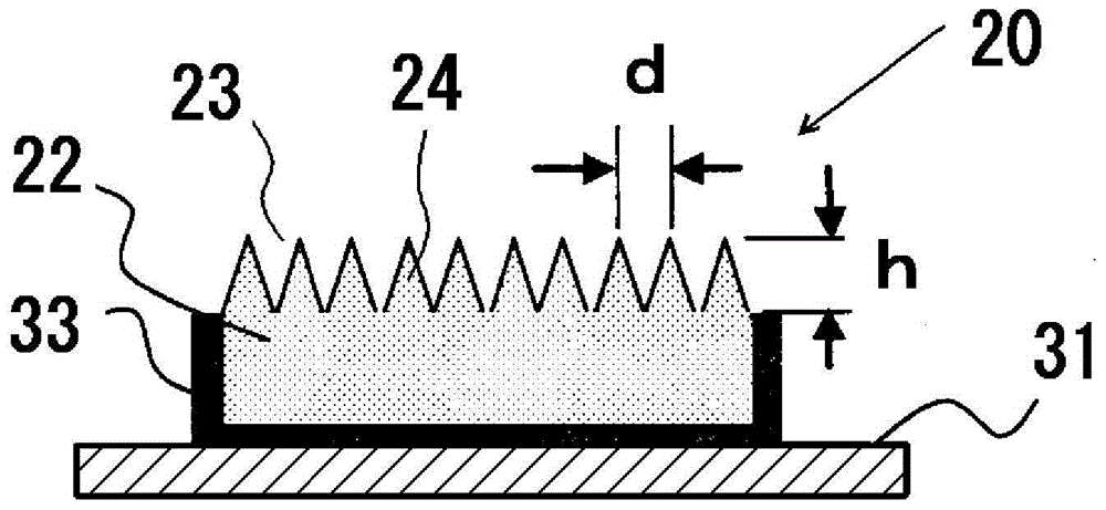
[0105] based on figure 2 With the configuration shown, a plurality of wavelength conversion members having a periodic structure on the surface were fabricated.

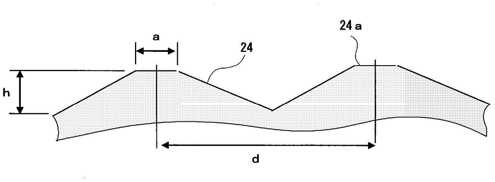
[0106] The periodic structures of the manufactured plurality of wavelength conversion members have different aspect ratios. These multiple wavelength conversion members are the following members: adjust the aspect ratio by changing the height (h) of the convex portion (24) in the range of 100 to 1100 nm, each having a conical convex portion (24), a period (d ) is 600 nm and has the following specifications.

[0107] Here, the period (d) is the magnitude of the range in which the diffraction of the fluorescent light emitted from the fluorescent material constituting the fluorescent member (22) occurs.

[0108] [substrate (31)]

[0109] Material: aluminum substrate, size: 25mm (length) x 25mm (width) x 1mm (thickness)

[0110] [fluorescence member (22)]

[0111] Material: LuAG: single crystal of Ce (composition = ...

experiment example 2

[0118] In Experimental Example 1, a fluorescent member with a refractive index of 2.0 was used as the fluorescent member (22) in the wavelength conversion member to make a plurality of wavelength conversion members, and to irradiate the manufactured plurality of wavelength conversion members with light having a peak wavelength of 465 nm as Except for the excitation light, the reflectance of light on the surface of the wavelength conversion member (LD reflectance) and the extraction efficiency of light were measured by the same method as in Experimental Example 1. show the result in Figure 8 . Should Figure 8 In , the measurement result of light reflectance (LD reflectance) is shown by a dotted line, and the measurement result of light extraction efficiency is shown by a solid line.

[0119] As a result, it was confirmed that in the wavelength conversion member, a periodic structure in which approximately tapered convex portions are arranged at a period of the size of the r...

experiment example 3

[0121] In Experimental Example 1, a fluorescent member with a refractive index of 2.3 was used as the fluorescent member (22) in the wavelength conversion member, and a plurality of wavelength conversion members were produced, and the wavelength conversion was measured by the same method as that of Experimental Example 1. Light reflectance (LD reflectance) and light extraction efficiency on the surface of the member. show the result in Figure 9 . Should Figure 9 In , the measurement result of light reflectance (LD reflectance) is shown by a dotted line, and the measurement result of light extraction efficiency is shown by a solid line.

[0122] As a result, it was confirmed that in the wavelength conversion member, a periodic structure in which approximately tapered convex portions are arranged at a period of the size of the range in which the diffraction of the fluorescence emitted from the phosphor constituting the fluorescent member occurs is formed on the excitation li...


PUM

PropertyMeasurementUnit
melting pointaaaaaaaaaa
thicknessaaaaaaaaaa
thicknessaaaaaaaaaa

Abstract

The purpose of the present invention is to provide a fluorescent-light-source device in which, when a wavelength conversion member is exposed to excitation light, backscattering of said excitation light is minimized and fluorescent light generated inside the wavelength conversion member is utilized effectively and emitted to the outside with high efficiency, yielding a high light-emission efficiency. This fluorescent-light-source device is characterized by the provision of a wavelength conversion member in the form of a florescent material that is excited by excitation light. This fluorescent-light-source device is further characterized in that: a periodic structure comprising substantially cone-shaped protrusions arrayed in a periodic fashion is formed on an excitation-light-receiving surface on the wavelength conversion member; the aspect ratio of said periodic structure, namely the quotient of the heights of the protrusions and the period of the periodic structure, is at least 0.2; and said period falls within a range within which fluorescent light emitted by the florescent material is diffracted.

Description

technical field [0001] The present invention relates to a fluorescent light source device that excites a phosphor with excitation light to emit fluorescence from the phosphor. Background technique [0002] For example, as a green light source used in a projector, conventionally known is a fluorescent light source device that irradiates a phosphor with laser light as excitation light and emits green light as fluorescence from the phosphor. As an example of such a fluorescent light source device, there is known a fluorescent light source device that includes a wavelength conversion member formed by coating a phosphor on the surface of a rotating wheel, and irradiates the wavelength conversion member with laser light in the blue region. , thereby generating light in the green region of the phosphor in the wavelength converting member (see Patent Document 1). [0003] However, a fluorescent light source device including a rotary wheel has problems in that the engine parts that ...

Claims


Application Information

Patent Timeline
Patent Type & Authority Applications(China)
IPC IPC(8): H01L33/50C09K11/00F21S2/00H01S5/02F21Y101/02G03B21/14H01S5/02218
CPCH01L33/505G03B21/204H01S5/022F21V5/005F21Y2115/30F21Y2115/10G02B5/0231F21K9/64F21V9/38F21V13/14H01S5/0087H01S5/02218
Inventor 井上正树北村政治芜木清幸
Owner USHIO DENKI KK
Why Eureka
Try Eureka