Hanging type insulating device of wet electric precipitator insulating box

A technology for electrostatic precipitators and insulating devices, which is applied in the field of hanging insulating devices for wet electrostatic precipitator insulation boxes, which can solve problems such as inconvenient installation and maintenance, increased costs, cost of construction and operation, and high frequency of failures, so as to improve the safety of use Performance and operating costs, improved recycling rate, stable and effective operation

Active Publication Date: 2015-10-14
SHANDONG GUOSHUN CONSTR GRP
View PDF9 Cites 7 Cited by
  • Summary
  • Abstract
  • Description
  • Claims
  • Application Information

AI Technical Summary

Problems solved by technology

[0004] (1) Quartz tubes are not easy to purchase and the price is high;
[0005] (2) The insulation box adopts electric heating, and the power consumption of each insulation box reaches more than 2 kilowatts, and the use cost is high;
[0007] (4) Long-term use is easy to form crystals in the quartz tube, which eventually leads to discharge breakdown and poor stability;
[0008] (5) The quartz tube is made of quartz burnt paper, with many defects. After processing, the surface is rough and easy to hang dust on the surface, which eventually leads to discharge
[0010] (1) The shell of the insulating box is relatively large, with a diameter of 2m, which increases the cost;
[0011] (2) The air volume is large, and the air volume of each insulation box is 700m 3

Method used


Image

  • Hanging type insulating device of wet electric precipitator insulating box
  • Hanging type insulating device of wet electric precipitator insulating box
  • Hanging type insulating device of wet electric precipitator insulating box

Examples


Embodiment Construction

[0034] In order to facilitate the understanding of the technical content of the present invention, the technical solutions thereof will be further described below in conjunction with the accompanying drawings.

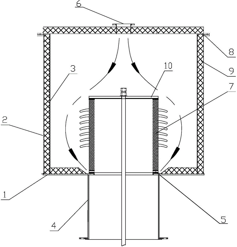
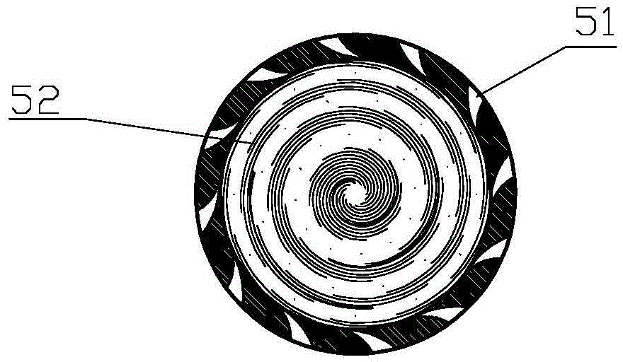
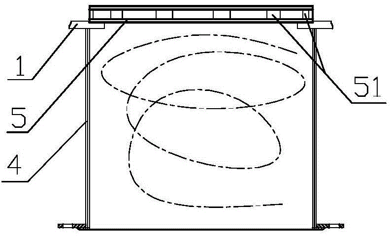
[0035] Such as Figure 1 to Figure 3 A suspension type insulating device for an insulating box of a wet electrostatic precipitator is shown, which includes an insulating cover, an insulating box base 4, a cyclone disk 5, an insulator 7 and a hanging rod. A hanging rod is arranged on the gland 10 of the insulator 7 . The insulating cover is arranged on the insulating box seat 4 through the chassis flange 1 .

[0036] Such as figure 1 As shown, the wall of the insulating cover is composed of an outer shell 2, an aluminum silicate fiber felt 9 and an inner shell 3, and the aluminum silicate fiber felt 9 is sandwiched between the outer shell 2 and the inner shell 3 Between, the outer casing 2 and the inner casing 3 are made of anti-corrosion metal plate material. A tap...


PUM


Abstract

A hanging type insulating device of a wet electric precipitator insulating box comprises an insulating cover, an insulating box base, an insulator, a hanging rod and a cyclone disc. The insulating cover is arranged on the insulating box base through a bottom disc flange. A conical hole is formed in the center of a bottom plate of the insulating cover, and the large opening end of the conical hole faces upwards. The cyclone disc is a circular ring. A plurality of air flues are evenly distributed on the circumferential wall of the cyclone disc. The air flues are inclined air flues with the large outer ports and the smaller inner ports and are consistent in inclination direction. The cyclone disc is arranged in the conical hole of the bottom plate of the insulating cover, is coaxial with the bottom disc flange and is arranged at the upper end of the bottom disc flange. The insulator is placed at the upper portion of the cyclone disc. An air inlet is formed in the top of the insulating cover. After entering a cavity of the insulating cover through the air inlet, the hot air enters the insulating box base through the air flues on the cyclone disc, and a backspin cyclone curtain can be formed after hot air enters the insulating box base; partition is formed for an insulating box base inner cavity where wet smoke invades, the short circuit between the hanging rod with high-voltage electricity and the cavity of the insulating cover so that electric conduction can be avoided, and the short-circuit access among the hanging rod, a gland and the insulating box base is blocked.

Description

technical field [0001] The invention relates to the field of insulating hanging devices, in particular to a hanging type insulating device for an insulating box of a wet electrostatic precipitator. Background technique [0002] The basic principle of wet electrostatic precipitator is the same as that of dry electrostatic precipitator. They both use high-voltage direct current to collect dust, and the voltage can reach about 80 kV. Compared with dry electrostatic precipitator, wet electrostatic precipitator deals with wet flue gas and has higher insulation requirements. There are two types of insulation currently in use: [0003] (1) Tapered quartz tube insulator, this method was first used in sulfuric acid, coking and other industries, and its use is relatively mature. Its shortcomings mainly include the following aspects: [0004] (1) Quartz tubes are not easy to purchase and the price is high; [0005] (2) The insulation box adopts electric heating, and the power consum...

Claims


Application Information

Patent Timeline
IPC IPC(8): B03C3/70
Inventor 郑忠才吕杨杨孙德山吕茂新赵民景敏王强亮
Owner SHANDONG GUOSHUN CONSTR GRP
Why Eureka
Try Eureka