Automatic feeding device of sliding table mechanical arm

A technology of automatic feeding and manipulator, applied in the direction of automatic in/out of workpieces, automatic/semi-automatic lathes, metal processing machinery parts, etc., can solve the problems of small applicability of the feeding device and low efficiency of manual feeding, and achieve a novel rotation mode. Ingenious, wide-ranging and easy-to-maintain effects

Active Publication Date: 2015-10-14
宁波麦科斯机器人科技有限公司
View PDF5 Cites 27 Cited by
  • Summary
  • Abstract
  • Description
  • Claims
  • Application Information

AI Technical Summary

Problems solved by technology

[0007] In order to solve the above-mentioned technical problems of low manual feeding efficiency and small applica...

Method used


Image

  • Automatic feeding device of sliding table mechanical arm
  • Automatic feeding device of sliding table mechanical arm
  • Automatic feeding device of sliding table mechanical arm

Examples


Embodiment 1

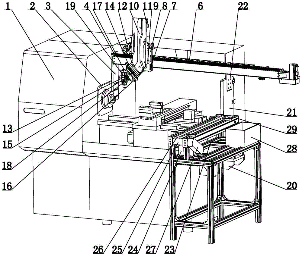
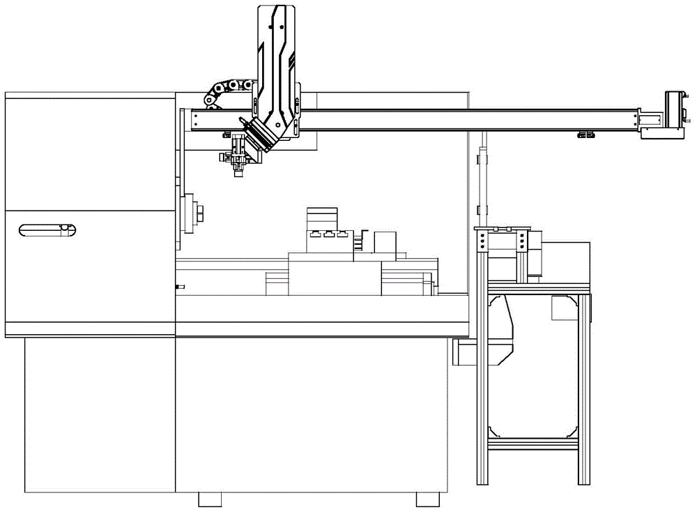
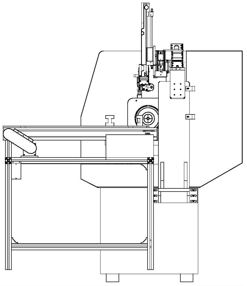
[0035] The sliding table manipulator automatic feeding device shown in Figures 1, 2, 3, 4, 5, 5, 6, 7, 8, 9, 10, 11, and 12 includes the main body of the machine tool 1, the electronic sliding table and the sliding table manipulator, The inner wall of the main body 1 of the machine tool is provided with a spindle head, the spindle head is provided with a spindle fixing plate 2, the spindle fixing plate 2 is provided with a spindle slide bracket 3, and the upper part of the spindle slide bracket 3 is provided with an electronic slider and a drag chain. 6, the slide table fixing plate 4, the right part of the electronic slide table is installed on the slide table support plate 21, the electronic slide table 5 outer wall is provided with a slide table dragging plate 7 connected, and the slide table dragging plate 7 is provided with a slide table manipulator, The sliding table manipulator includes a manipulator movable plate 10, a rodless cylinder 9 and a rodless cylinder fixing pl...

Embodiment 2

[0041] As shown in Figures 13, 14, and 15, the difference between this embodiment and Embodiment 1 is that the sliding and fixing block structure includes a sliding and fixing block 34, the driving structure includes a servo motor a49, and the tail end fixing block 41 is connected with the motor fixing block 48 , the motor fixing block 48 is provided with a servo motor a49, the servo motor shaft of the servo motor a49 is provided with a synchronous wheel a47, the same side of the synchronous wheel a47 is provided with a synchronous wheel b46, and a rotating belt is provided between the synchronous wheel a47 and the synchronous wheel b46, synchronously Wheel b46 passes through motor fixed block 48 and is connected with synchronous wheel c45, and described synchronous wheel c45 is positioned at tail end fixed block 41, and cover block 43 is housed on tail end fixed block 41, and casing 44 is housed on motor fixed block 48, front fixed The block 37 is provided with a rotating shaf...

Embodiment 3

[0043] As shown in Figures 16, 17, 18, and 19, the difference between this embodiment and Embodiment 1 is that the sliding and fixing block structure includes a sliding and fixing block 34, the driving structure includes a servo motor b56, and the motor head of the servo motor b56 passes through a coupling 53 Connect the screw mandrel 51, the screw mandrel 51 is located on the front fixed block 37 and the rear fixed block 38, the screw mandrel 51 is provided with a screw mandrel nut 52, the front fixed block 37 inner wall is provided with a buffer head 55, slides on the fixed block 34 A plastic cover bar 54 is provided, a plastic cover plate 57 is provided on the back of the coupling 53 , a slide table dust-proof cover bar 58 is provided on the slide table base 31 , and a guide rail slider 59 is provided on the slide fixing block 34 .

[0044] When in use, the sliding and fixing block 34 is driven to move back and forth by the screw rod 51 .


PUM


Abstract

The invention relates to a mechanical transmission device, in particular to an automatic feeding device of a sliding table mechanical arm. The automatic feeding device of the sliding table mechanical arm comprises a machine tool body, an electronic sliding table and the sliding table mechanical arm. A spindle headstock is arranged on the inner wall of the machine tool body. A spindle fixing plate is arranged on the spindle headstock. A spindle sliding table support is arranged on the spindle fixing plate. A sliding table fixing plate is arranged on the upper portion of the spindle sliding table support. The right portion of the electronic sliding table is arranged on a sliding table support plate. A sliding table dragging plate connected with the electronic sliding table is arranged on the outer wall of the electronic sliding table. A sliding table mechanical arm is arranged on the sliding table dragging plate and comprises a mechanical arm moving plate, a rodless cylinder and a rodless cylinder fixing plate. The automatic feeding device of the sliding table mechanical arm has the beneficial effects that a rotation mode is novel and exquisite, work is precise, and efficiency is high; mechanical operation is adopted, and product uniformity is high and stable

Description

technical field [0001] The invention relates to a mechanical transmission device, in particular to an automatic feeding device for a sliding table manipulator. Background technique [0002] Quick connectors include hydraulic quick connectors and various fluid quick connectors, which are a quick connection or disconnection of pipelines, [0003] Connection device for quick disassembly. Since the quick connector has a two-way check function and the pipeline is disconnected without leakage, it is suitable for petroleum, [0004] It is widely used in metallurgy, hydropower, engineering machinery, ships, electromechanical equipment and other fields. Part of the joint process is performed on the lathe [0005] The joints are manually placed in the processing position, and the props are processed, but the efficiency of manual loading is low and it is easy for personnel [0006] Fatigue, in addition, some feeding devices are inconvenient to operate and consume a lot of energy, a...

Claims


Application Information

Patent Timeline
IPC IPC(8): B23B13/02B23Q7/04
CPCB23B13/02B23Q7/04B23Q2707/003
Inventor 冯翔宇胡良明
Owner 宁波麦科斯机器人科技有限公司
Why Eureka
Try Eureka