Bi-plane parallel mechanism capable of achieving plane two-dimensional positioning and spatial two-dimensional orientation

A two-plane, two-plane technology, applied in the field of parallel robots, can solve the problems of medical robots with complex configuration, low surgical safety, and low operating precision, and achieve flexible and convenient control, good rigidity performance, and high positioning accuracy Effect

Active Publication Date: 2015-10-14
HARBIN SIZHERUI INTELLIGENT MEDICAL EQUIP CO LTD
View PDF5 Cites 10 Cited by
  • Summary
  • Abstract
  • Description
  • Claims
  • Application Information

AI Technical Summary

Problems solved by technology

[0005] In order to solve the problems of low operation precision, poor reliability and low operation safety caused by the complex configuration, large volume and high operation difficulty of the existing medical robots for minimally invasive spinal surgery, the present invention proposes a two-dimensional Biplanar Parallel Mechanism for Positioning and Spatial Orientation

Method used


Image

  • Bi-plane parallel mechanism capable of achieving plane two-dimensional positioning and spatial two-dimensional orientation
  • Bi-plane parallel mechanism capable of achieving plane two-dimensional positioning and spatial two-dimensional orientation
  • Bi-plane parallel mechanism capable of achieving plane two-dimensional positioning and spatial two-dimensional orientation

Examples


specific Embodiment approach 1

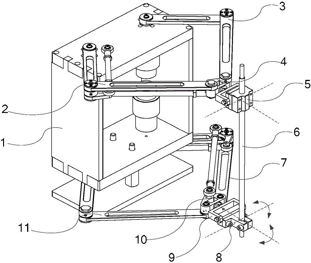
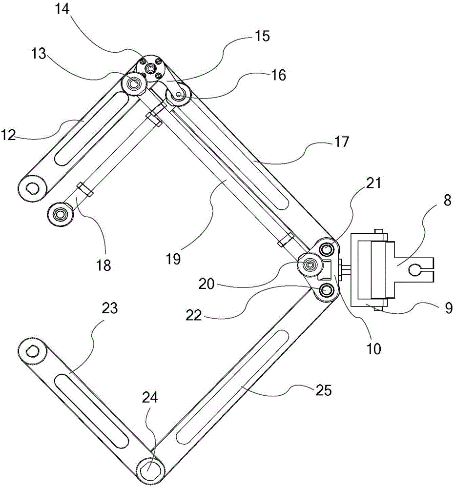
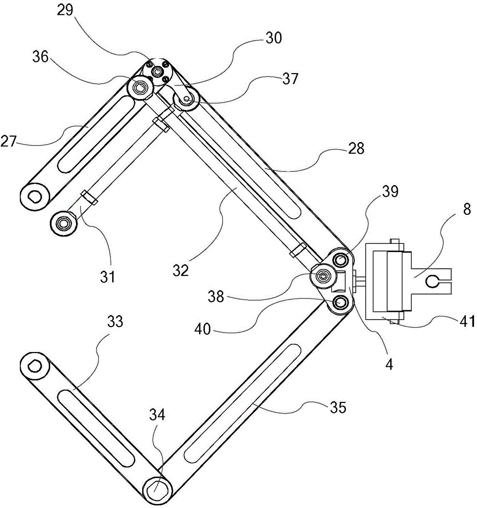
[0058] Specific implementation mode 1, refer to Figure 1 to Figure 8 Describe this embodiment mode, a two-plane parallel mechanism that can realize plane two-dimensional positioning and space two-dimensional orientation described in this embodiment mode, it includes an upper plane driving mechanism, a lower plane driving mechanism, a frame 1, a driving device 26, Upper plane connector, lower plane connector and end device 6;

[0059] Frame 1 comprises upper frame 1-1, left frame 1-2, lower frame 1-3 and right frame 1-4; Upper frame 1-1, left frame 1-2, lower frame 1-3 and right frame 1- 4 connected end to end to form a hollow cuboid frame or square frame;

[0060] The upper plane driving mechanism is coaxially connected with the terminal instrument 6 through the upper plane connecting piece; the lower plane driving mechanism is coaxially connected with the terminal instrument 6 through the lower plane connecting piece; the upper plane driving mechanism and the lower plane dr...

specific Embodiment approach 2

[0068] Specific implementation mode two, refer to Figure 8 Describe this embodiment. This specific embodiment is a further description of a dual-plane parallel mechanism that can realize two-dimensional positioning on a plane and two-dimensional orientation in space as described in Embodiment 1. In this embodiment, the driving device 26 is four Two are used to drive the upper plane drive mechanism, and two are used to drive the lower plane drive mechanism.

specific Embodiment approach 3

[0069] Specific implementation mode three, refer to Figure 8 Describe this embodiment. This specific embodiment is a further description of a dual-plane parallel mechanism that can realize plane two-dimensional positioning and spatial two-dimensional orientation described in the second specific embodiment. In this embodiment, four driving devices 26 Both are located inside the frame 1, and the two driving devices 26 for driving the upper plane driving mechanism are fixed on the upper frame 1-1; the two driving devices 26 for driving the lower plane driving mechanism are fixed on the lower frame 1-1. 3; the driving device 26 is a motor.


PUM


Abstract

The invention relates to the technical field of parallel robots, in particular to a bi-plane parallel mechanism capable of achieving plane two-dimensional positioning and spatial two-dimensional orientation. The bi-plane parallel mechanism aims to solve the problems that an existing medical robot for minimally-invasive spine surgery is low in precision, poor in reliability and low in surgical safety due to the complex structure, the large size and high operating difficulty, and is used for completing positioning and orientation of a tail-end instrument of a medical robot for minimally-invasive spine surgery. The bi-plane parallel mechanism is composed of an upper plane driving mechanism, a lower plane driving mechanism and the tail-end instrument. The two plane mechanisms are connected with the tail-end instrument through U pairs, and the upper plane U pair can slide along the axis of the instrument. Each plane driving mechanism is formed by sequentially connecting four rods through connecting shafts or fixing shafts. The bi-plane parallel mechanism is also suitable for completing plane two-dimensional positioning and spatial two-dimensional orientation for other tools.

Description

technical field [0001] The invention relates to the technical field of parallel robots. Background technique [0002] The moving platform and the fixed platform of the parallel robot are connected by more than two independent kinematic chains. Under the kinematic input of each chain, it is convenient to provide multi-pose kinematic forms, with high kinematic precision, fast dynamic response, and strong carrying capacity. Therefore, the parallel robot is more suitable as the basic construction form of the positioning and orientation mechanism. In minimally invasive spinal surgery, the types of surgery involved include pedicle screw fixation, percutaneous vertebroplasty, percutaneous laminar decompression, etc. Mistakes may cause damage to the spinal cord or nerve roots, resulting in paralysis of the lower limbs or even death. [0003] The traditional manual minimally invasive surgery method requires the doctor to have a high level of operating skills, but the surgical metho...

Claims


Application Information

Patent Timeline
Patent Type & Authority Applications(China)
IPC IPC(8): B25J9/00
Inventor 于洪健杜志江董为王永锋
Owner HARBIN SIZHERUI INTELLIGENT MEDICAL EQUIP CO LTD
Why Eureka
Try Eureka