Multifunctional electro-hydraulic robot

A hydraulic robot, multi-functional technology, applied in the direction of manipulators, program control manipulators, claw arms, etc., to achieve advanced functions, reduce costs, save human resources and labor costs

Inactive Publication Date: 2017-03-08
重庆今古奇观科技有限公司
View PDF6 Cites 0 Cited by
  • Summary
  • Abstract
  • Description
  • Claims
  • Application Information

AI Technical Summary

Problems solved by technology

[0003] The technical problem to be solved by the multifunctional electrohydraulic robot of the present invention is that the multifunctional electrohydraulic robot of the present invention adopts the girder balance weight axle 1 or the suspension beam bracket lifting car control platform 2 or the Horizontally rotate the outer box body 3 of the multi-section mechanical telescopic arm or the folding fork manipulator 4 of the first telescopic arm or the folding and clamping manipulator 5 of the second telescopic arm or the rotating luffing grip of the third telescopic arm With the overall structural conception of characteristic technologies such as manipulator 6 and fire extinguisher 7, it has the advantages of multiple changing functions and a wide range of applications. It is not only a loading, unloading, handling, and stacking robot for warehousing, warehouses, and logistics. It can also be used for warehousing, warehouse, and logistics. The first-line operating robot makes up for the lack of a single function of the manipulator of similar robotic equipment. This robot integrates a low center of gravity, vertical lifting, horizontal rotation and horizontal telescopic multi-section manipulator. It is characterized in that the horizontal rotation multi-section mechanical telescopic Arm outer box 3 or the first telescopic arm folding fork manipulator 4 or the second telescopic arm folding holding manipulator 5 or the third telescopic arm rotating luffing grasping manipulator 6 Each telescopic manipulator is different functional manipulator

Method used


Image

  • Multifunctional electro-hydraulic robot
  • Multifunctional electro-hydraulic robot
  • Multifunctional electro-hydraulic robot

Examples


Embodiment 1

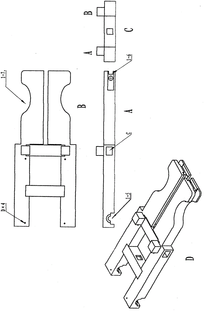
[0046] Embodiment 1, see Picture 1-1 , in this case Picture 1-1 It is a structural schematic diagram of the girder counterweight vehicle bridge 1. There are A and B pile heads connected and positioned with the outer mast 1-1 on both sides of the H beam, and there is a leg on both sides of the girder counterweight vehicle bridge 1. Telescopic hole C, installation of telescopic legs 1-4, the front end of the beam balance weight axle 1 is provided with grooves 1-6 and elliptical grooves 1-7 for installing the front drive wheel shaft and steering hydraulic cylinder, the beam balance weight The rear half of the vehicle axle 1 has four screw holes D connecting the trough type balance weight frame 1-3, and the rear end of the crossbeam balance weight vehicle axle 1 has a bearing groove 1-5 for installing the driving wheel shaft and the bearing seat.

Embodiment 2

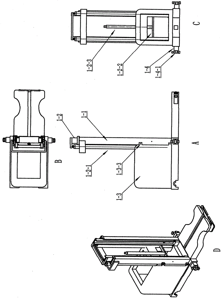
[0047] Embodiment 2, Figure 1-2 It is the combined structure diagram of the girder counterweight axle lifting frame

[0048] There are earrings 1-3-3 connected with the outer mast on the trough-shaped counterweight frame 1-3, and there are four screw holes at the bottom of the trough-shaped counterweight frame 1-3 and the screw holes D of the girder counterweight axle 1 In this way, a double balance weight protection with a low center of gravity is formed, which ensures that the telescopic mechanical arm will not roll over when the hand rotates left and right. The inner mast lifting hydraulic cylinder 1-2-1 is installed in the groove In the groove before the type counterweight frame 1-3, the inner mast lifting hydraulic cylinder 1-2-1 is connected with the top beam of the inner mast, and the lower connecting beam 1-2-2 of the inner mast The lifting hydraulic cylinder 1-2-3 of the beam bracket lifting trolley is installed on it, and the telescopic outrigger 1-4 is connected w...

Embodiment 3

[0049] Embodiment 3, diagram 2-1 , Figure 2-2 It is the combination structure diagram of the control platform 2 of the suspension cantilever bracket lifting trolley

[0050] The lifting slide 2-1 is connected with the double H-shaped cantilever bracket 2-1-2, the bearing seat 2-1-3, the hydraulic rack cylinder 2-1-4, and the pinion 2-1-5. The storage battery 2-2 and the hydraulic package 2-2-1 are installed at the tail of the control platform to ensure the balance and stability of the control platform 2-3 and the multi-section telescopic boom. The instrument panel integrates the electric control system 2-3-2 and Steering wheel 2-3-1 is installed on the front end of described control platform 2-3, helps operator to operate conveniently.


PUM


Abstract

The invention discloses a novel multifunctional electro-hydraulic robot. Outer portal frames are mounted on positioning pile head points A and B at the two sides of a beam H of a chassis girder counterweight axle (1) respectively; a lifting trolley control platform (2) is mounted on a portal frame type lifting suspension bracket; a rotary tank body (3) of a multi-section rotary telescopic boom mechanical hand is fixedly connected with a bearing on a lifting trolley bracket; a rotary telescopic boom outer tank body (3) or a fork mechanical hand (4) or a clamping mechanical hand (5) is mutually connected; the telescopic boom is firstly inserted into the tank body and then is clamped with slide wheels (3-1-4) on the four corners; a telescopic hydraulic cylinder (3-1-2) mounted in the telescopic boom is connected with a lug ring at the front lower end outside the telescopic boom to realize a telescopic function; and a rotary holding mechanical hand (6) or a fire extinguisher (7) is internally mounted in a telescopic tank of the mechanical hand (5). According to the novel robot disclosed by the invention, each section of the telescopic boom mechanical hand is different in function of grabbing goods, and therefore, the novel multifunctional electro-hydraulic robot is the most advanced robot in the present world.

Description

technical field [0001] The invention relates to an electrohydraulic robot, in particular to a multifunctional electrohydraulic loading and unloading robot equipment Background technique [0002] The overall structural assembly of this robot is composed of steel structure welding components and hydraulic cylinder connections. Compared with traditional and existing robot loading and unloading equipment, it has the advantages of more functional changes, covering a wide range of industries, etc. The overall rigid structure is strong, and the center of gravity It has the characteristics of low weight, good stability of moving balance, strong safety and reliability, multi-section mechanical telescopic arm and manipulator with many changing functions. It has the powerful power and load capacity of the machine, and the flexibility of manpower. It has a simple structure, environmental protection and energy saving. , easy to manufacture, low cost and other advantages. Contents of th...

Claims


Application Information

Patent Timeline
Patent Type & Authority Patents(China)
IPC IPC(8): B25J9/08B25J18/02
Inventor 孙德华
Owner 重庆今古奇观科技有限公司
Why Eureka
Try Eureka