
Vane carrier for compressor or turbine section of axial turbo machine

A compressor, carrier technology, applied in parts of pumping devices for elastic fluids, machines/engines, mechanical equipment, etc., can solve the problems of time-consuming, expensive manufacturing of multi-layer components, etc.

Inactive Publication Date: 2015-10-14
ANSALDO ENERGIA IP UK LTD
View PDF7 Cites 4 Cited by
  • Summary
  • Abstract
  • Description
  • Claims
  • Application Information

AI Technical Summary

Problems solved by technology

Although the use of expensive high-temperature materials is reduced, multi-layer components are still expensive and time-consuming to manufacture

Method used


Image

  • Vane carrier for compressor or turbine section of axial turbo machine
  • Vane carrier for compressor or turbine section of axial turbo machine
  • Vane carrier for compressor or turbine section of axial turbo machine

Examples


Embodiment Construction

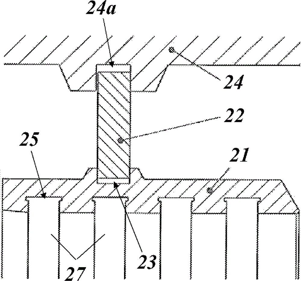
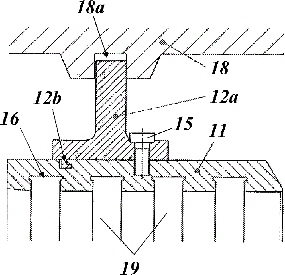
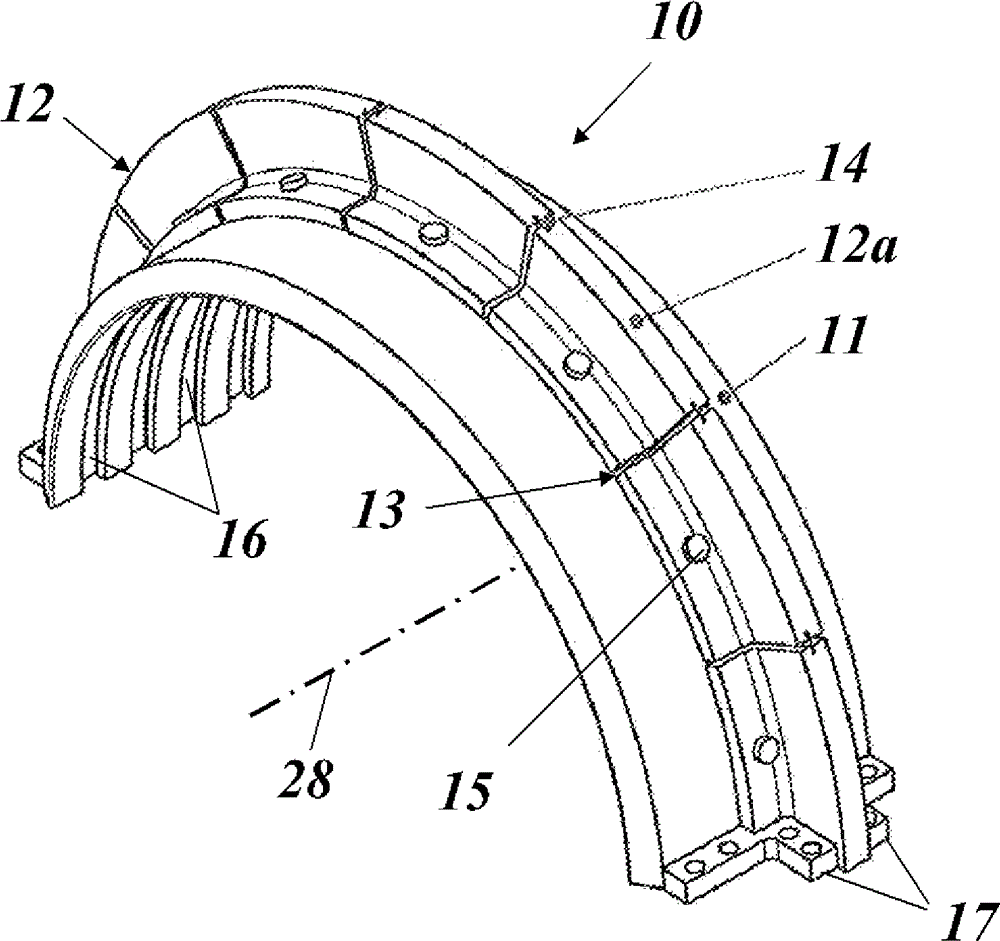
[0048] Low thermal expansion (low CTE) materials bring significant benefits in reduction of compressor clearances. Unfortunately, these materials are only very expensive nickel alloy steel. The hybrid design of the vane carrier according to the invention allows the application of low thermal expansion materials for the main cylindrical portion of the carrier, while the less critical support and sealing structures are formed from standard inexpensive steel.

[0049] Both design proposals have the same rationale of using low thermal expansion material for the cylindrical section and standard low alloy steel for the support section of the vane carrier.

[0050] In both designs, as in figure 1 and figure 2 (first design) and image 3 and Figure 4 As shown in (the second design), the respective cylindrical portions 11 and 21 of the vane carriers 10 and 20 are respectively formed of a low thermal expansion material to reduce the operating clearance of the compressor. The purp...


PUM


Abstract

A vane carrier (10) for a compressor or a turbine section of an axial turbo machine, especially one of a gas turbine, steam turbine, compressor, expander, comprises least a first and second functional means (11, 12), whereby said first functional means (11) is a cylinder made of a material with a coefficient of thermal expansion (CTE) below 1,3 x 10 -5 [1 / K], which cylinder is provided for carrying a plurality of vanes on its inner side, and whereby said second functional means (12) is a support structure made of a material different to and less expensive than the material of said first functional means (11), which support structure (12) is provided for defining an axial and lateral position of said first functional means (11) within an outer casing (18) of said axial turbo machine. The advantage is a reduced clearance at moderate cost.

Description

technical field [0001] The present invention relates to the technology of turbomachines. It relates to a vane carrier for a compressor or a turbine section of an axial turbine according to the preamble of claim 1 . Background technique [0002] A gas turbine typically includes a compressor section, a combustor, and at least one turbine. Within the compressor section, alternating rows of running vanes and guide vanes interact with the combustion air as it is compressed in the annular gas passage for use in the compressor to burn fuel. When mounting the running blades on the central rotor, the guide vanes are fixed and mounted on a suitable compressor vane carrier (CVC), which concentrically surrounds and delimits the gas passages. [0003] It is known in the art to use CVCs formed entirely of low thermal expansion materials such as nickel-based alloys. This design is advantageous when applied to industrial (stationary) gas turbines (GT) of eg 50 MW power, as it leads to hi...

Claims


Application Information

Patent Timeline
IPC IPC(8): F01D9/04F04D29/40
CPCF01D9/04F01D9/041F01D9/042F01D11/005F01D11/18F01D25/246F01D25/265F04D29/541F05D2220/31F05D2220/32F05D2230/90F05D2240/12F05D2240/14F05D2300/171F05D2300/502F05D2300/50212
Inventor R.普兹拜O.J.塔亨伊G.卡塔迪
Owner ANSALDO ENERGIA IP UK LTD
Features
  • Generate Ideas
  • Intellectual Property
  • Life Sciences
  • Materials
  • Tech Scout
  • Unparalleled Data Quality
  • Higher Quality Content
  • 60% Fewer Hallucinations
Learn More